
Method for operating a vibratory measuring instrument, and corresponding instrument

a technology of vibratory measuring and measuring instruments, applied in the direction of liquid/fluent solid measurement, volume variation compensation/correction apparatus, direct mass flowmeters, etc., can solve the problem of different oscillation modes that need to be implemented, and achieve the effect of making the signal evaluation more precis

Inactive Publication Date: 2010-01-21
ABB PATENT GMBH
View PDF5 Cites 53 Cited by
  • Summary
  • Abstract
  • Description
  • Claims
  • Application Information

AI Technical Summary

Benefits of technology

[0010]An aspect of the present invention is to provide a method for operation of an instrument of the vibration type, by means of which the oscillation excitation of characteristic physical operating parameters is simplified, and the signal evaluation is made more precise.
[0039]The advantage of the solution according to the invention is, in particular, that the complete spectrum of the oscillation behavior of the measurement tube can be used to obtain reliable information about characteristic physical operating parameters, even though the oscillation excitation of the measurement tube may also be only over a narrow bandwidth. This makes it possible to compensate for different cross-sensitivities and to diagnose the instrument integrity. This is because higher-frequency oscillations and lower-frequency oscillations occur in addition to the resonant frequency in the broadband frequency range of the oscillation behavior of the measurement tube, and have harmonic or sub-harmonic features which are also indirectly suitable as an indicator of ageing processes and the like.

Problems solved by technology

However, the method described above has the disadvantage that different oscillation modes need to be implemented in order to obtain the desired characteristic physical operating parameters.

Method used


Image

  • Method for operating a vibratory measuring instrument, and corresponding instrument
  • Method for operating a vibratory measuring instrument, and corresponding instrument

Examples


Embodiment Construction

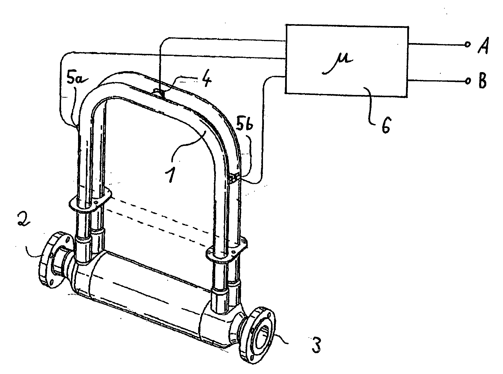
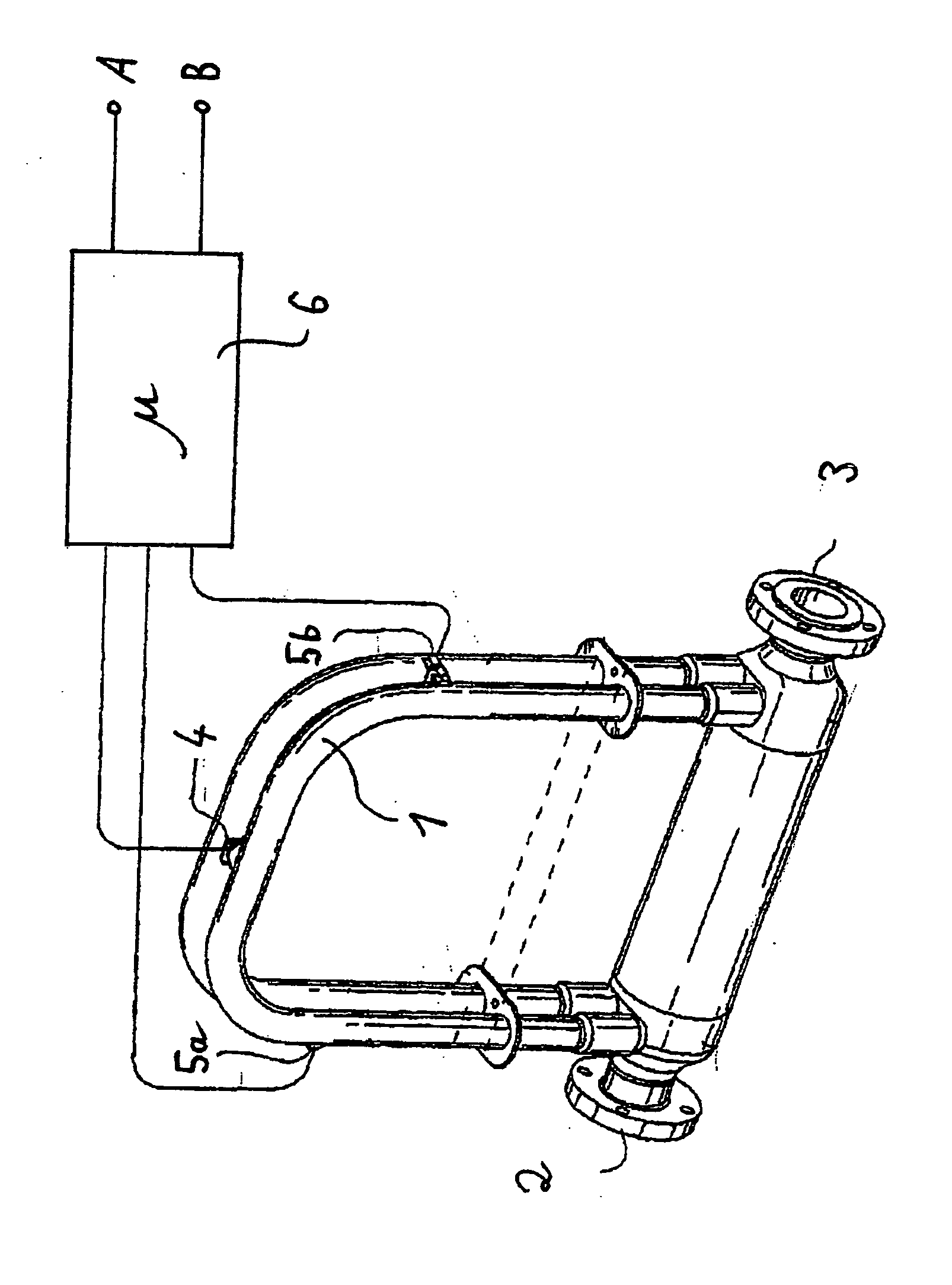
[0044]As can be seen from the FIGURE, the Coriolis flowmeter comprises a curved measurement tube 1 which is arranged in a duplicated form and is arranged between an inlet-flow flange 2 and an outlet-flow flange 3. The measurement medium, which flows between the inlet-flow flange 2 and the outlet-flow flange 3, including the measurement tube 1, is caused to oscillate mechanically, together with the measurement tube 1, by an oscillation production unit 4. A split sensor unit 5a, 5b, which is fitted to the measurement tube 1 on both sides of the oscillation production unit 4 in the indicated example, detects the oscillation behavior of the measurement tube 1 as a response to the oscillation excitation. The measurement signal from the sensor unit 5a, 5b is supplied to the input side of an electronics unit 6, for signal processing.

[0045]While the oscillation production unit 4 excites the measurement tube 1 only in a narrowband manner at one of the possible frequencies, the electronics un...


PUM


Abstract

A method for operation of a vibratory measurement instrument comprises flowing a fluid through at least one measurement tube; causing the measuring tube to oscillate mechanically using an oscillation production unit; detecting an oscillation behavior of the tube using at least one oscillation sensor; determining at least one of a mass flow, a viscosity, and a density in a narrowband frequency range based on the oscillation behavior; evaluating at least one of the mass flow, the viscosity, and the density using signal processing of an electronics unit; and evaluating the oscillation behavior at least at times in a broadband frequency range using the electronics unit.

Description

[0001]This is a U.S. National Phase Application under 35 U.S.C. § 171 of PCT / EP2007 / 011237, filed on Dec. 20, 2007, which claims priority to German Application No. DE 10 2006 060 595.0, filed Dec. 21, 2006 and DE 10 2007 061 690.4, filed on Dec. 19, 2007. The International Application was published in German on Jul. 3, 2008 as WO 2008 / 077574 under PCT article 21 (2).[0002]The present invention relates to a method for operation of an instrument of the vibration type, in which a fluid medium can flow through at least one measurement tube, which can be caused to oscillate mechanically via an oscillation production unit, with the oscillation behavior, which varies as a function of the flow and / or the viscosity and / or the density of the fluid medium, being detected by at least one oscillation sensor in order to determine the mass flow and / or the viscosity and / or the density in a narrowband frequency range, and then being evaluated by signal processing by means of an electronics unit.[000...

Claims


Application Information

Patent Timeline
Patent Type & Authority Applications(United States)
IPC IPC(8): G01F1/84
CPCG01F1/8413G01F1/8436G01F25/0007G01F15/02G01F1/8477G01F25/10
Inventor GEBHARDT, JOERGKASSUBEK, FRANKDEPPE, LOTHARKELLER, STEFFENFRIEDRICHS, RENE
Owner ABB PATENT GMBH
Learn More