Cylinder head structure for internal combustion engine

a technology of internal combustion engine and cylinder head, which is applied in the direction of cylinders, machines/engines, mechanical equipment, etc., can solve the problems of air flowing through the space above the cylinder head that is not taken into account, the flow of air directed into the space above the cylinder head is not uniformly distributed, and the air flowing through the space above the cylinder head may stagnate, etc., to achieve a high degree of freedom in design, prevent the effect of stagnation and low flow resistan

Inactive Publication Date: 2010-01-21
TOYOTA JIDOSHA KK
View PDF6 Cites 2 Cited by
  • Summary
  • Abstract
  • Description
  • Claims
  • Application Information

AI Technical Summary

Benefits of technology

[0010]As described above, air evenly flows in the gas flow passage space, which exhibits particularly low flow resistance. Therefore, air first spreads substantially uniformly and sufficiently in the entire gas flow passage space. Air then starts flowing out from this entire gas flow passage space to other regions of the covered space. In this case, air flows in the lateral direction and hence covers a relatively short distance to sufficiently flow through the entire covered space above the cylinder head. Accordingly, air substantially uniformly spreads in the entire covered space. Thus, air reaches corner portions of the space and the like as well and can be prevented from stagnating.
[0015]As described above, air evenly spreads in all the regions of the gas flow passage space, which exhibit particularly low flow resistance, in the longitudinal direction, flows out from all the discontinuously arranged regions of the gas flow passage space as well in the lateral direction, and covers a sufficiently short distance to flow through the entire covered space above the cylinder head. Thus, air sufficiently reaches corner portions of the covered space and the like as well and can be prevented from stagnating.
[0016]As described above, the gas flow passage space is arranged over the entire length or substantially over the entire length in the longitudinal direction, and extends discontinuously in the lateral direction. Air can thereby be uniformly spread in the covered space above the cylinder head covered with the head cover while maintaining a high degree of freedom in the design of the internal combustion engine.

Problems solved by technology

However, it is difficult to uniformly spread air directed into the space above the cylinder head simply by providing the dam between the cylinder head side and the chain case side.
That is, the flow of air directed into the space above the cylinder head is not sufficiently taken into account.
Therefore, the air flowing through the space above the cylinder head may stagnate.

Method used


Image

  • Cylinder head structure for internal combustion engine
  • Cylinder head structure for internal combustion engine
  • Cylinder head structure for internal combustion engine

Examples


first embodiment

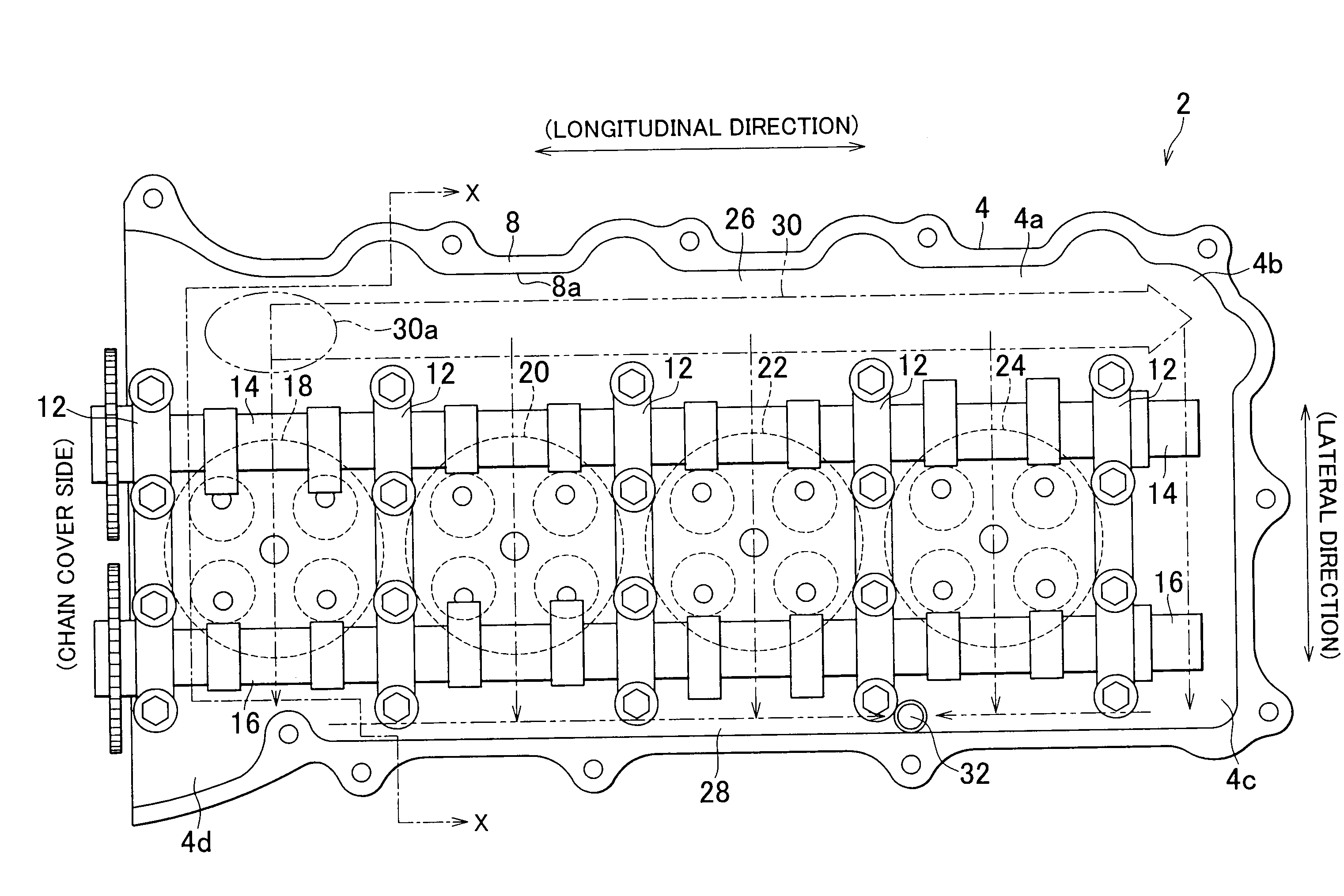
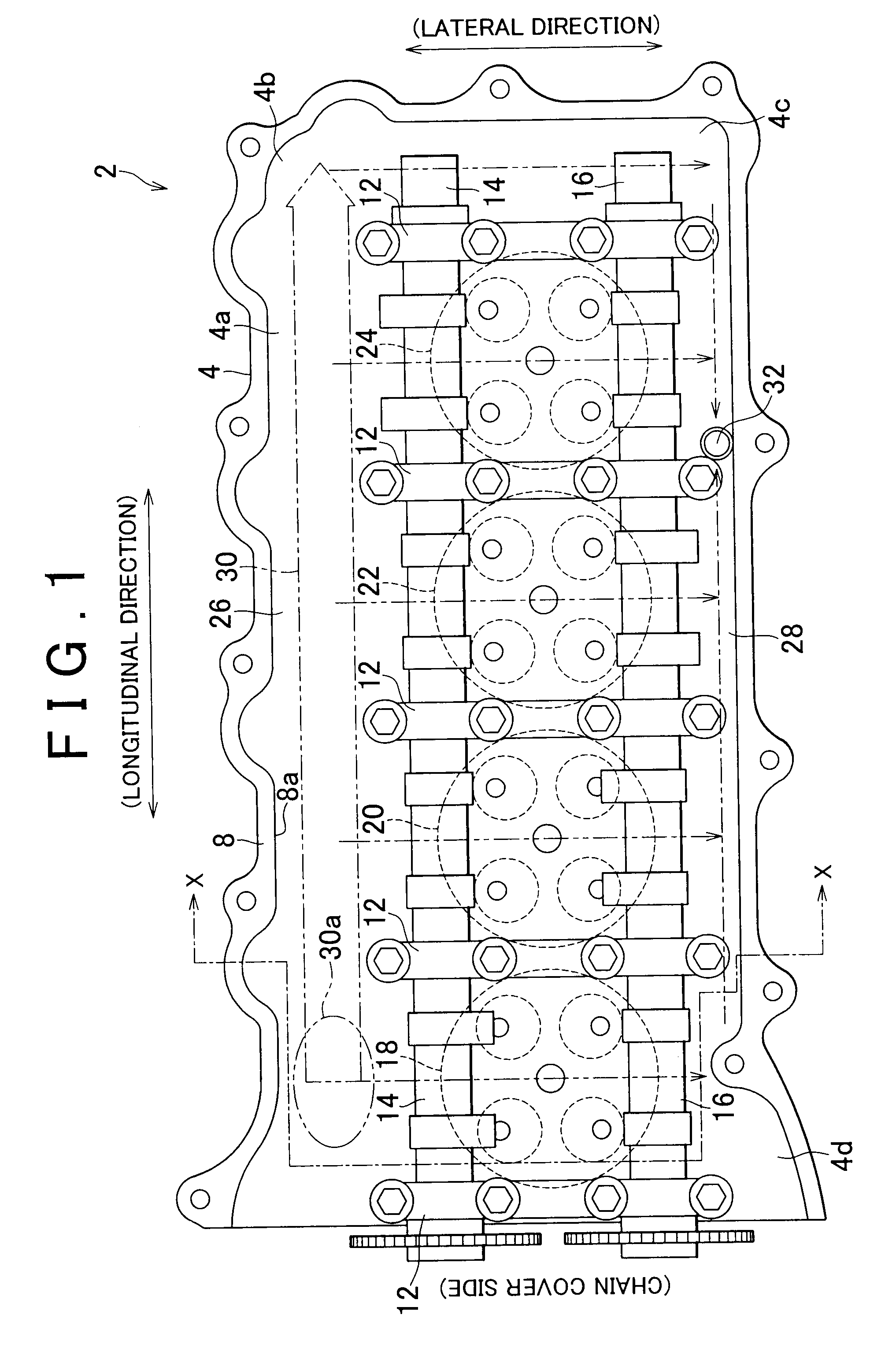
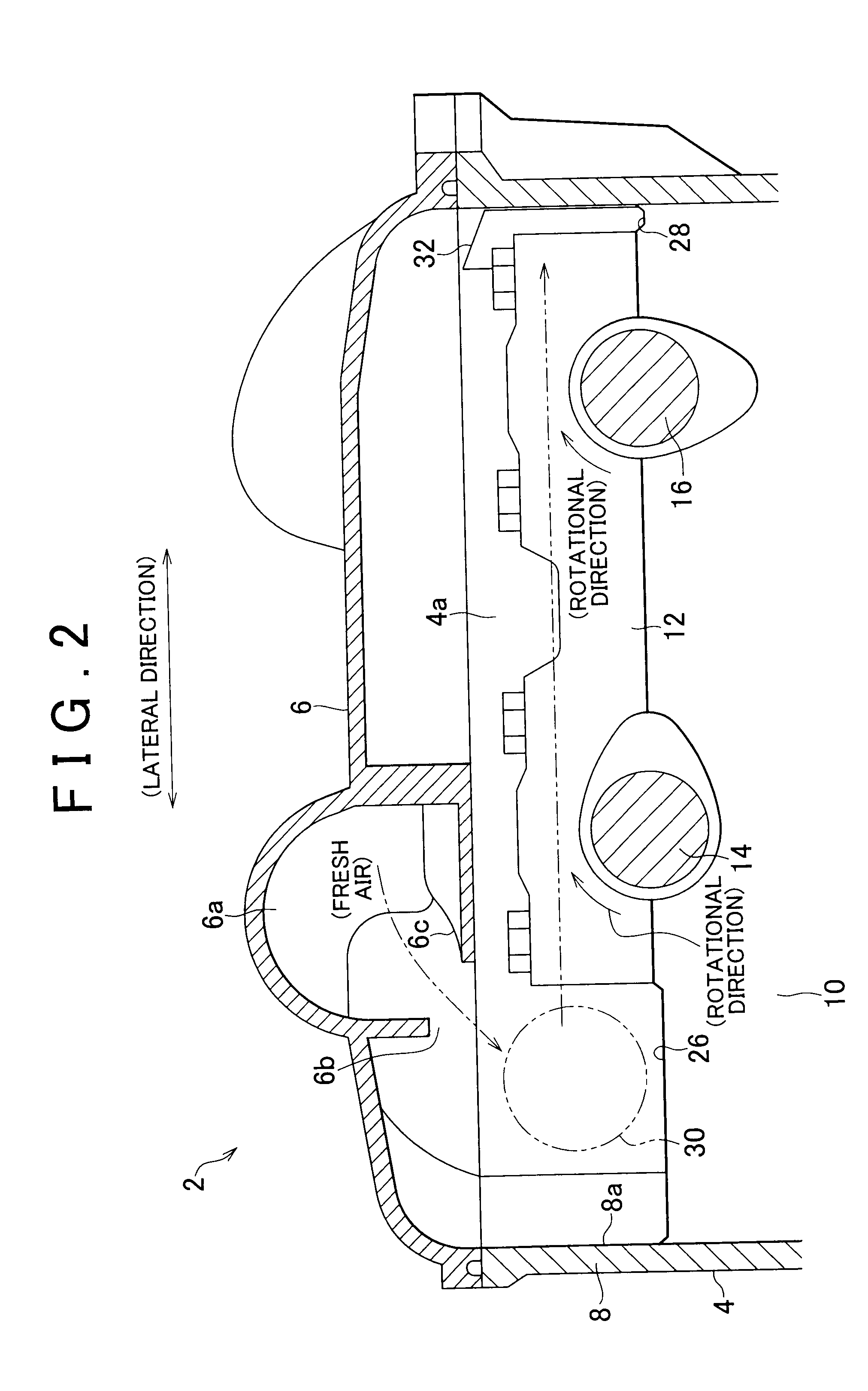
[0024]FIG. 1 is a plan view showing an overall construction of a cylinder head4 for an internal combustion engine 2 according to the invention. FIG. 2 is a cross-sectional view taken along a line X-X of FIG. 1. The cross-sectional view of FIG. 2 shows a state in which a head cover 6 is mounted. Arrows indicated by alternate long and two short dashes lines represent the flow of gas. In the other drawings as well, arrows indicated by alternate long and two short dashes lines represent the flow of gas.

[0025]Five journal bearings 10 are formed in the cylinder head 4 inside a deck portion 8 that surrounds the outer periphery of the cylinder head 4. An intake camshaft 14 and an exhaust camshaft 16 are rotatably supported by fastening five cam caps 12 by means of boltscamshaft.

[0026]The internal combustion engine 2 may be a four-cylinder gasoline engine or a four-cylinder diesel engine. In the direction in which respective cylinders 18, 20, 22, and 24 are arranged, a journal bearing 10 is ...

second embodiment

[0039]In an internal combustion engine 102 according to the invention, as shown in a plan view of FIG. 3, two partial gas flow passage spaces 130a and 130b are formed in a covered space 104a above a cylinder head 104. The two partial gas flow passage spaces 130a and 130b together form a gas flow passage space 130 extending from a fresh air introduction position 130c over the entire length in the longitudinal direction of the covered space 104a. However, the two partial gas flow passage spaces 130a and 130b are spaced apart from each other in the lateral direction, so that the gas flow passage space 130 is discontinuous.

[0040]The partial gas flow passage space 130b is the downstream region of the gas flow passage space 130 and is arranged near the exhaust camshaft 116. Therefore, the fresh air discharge port 132 is formed at the end opposite the partial gas flow passage space 130b in the lateral direction.

[0041]The head cover corresponds in shape to the cylinder head 104, but is basi...

fourth embodiment

[0053]the invention shows an example of a cam carrier 302 arranged between a head cover 306 and the cylinder head 304 of an internal combustion engine as shown in FIGS. 5 and 6. FIG. 5 is a plan view showing an overall construction of the cam carrier 302. FIG. 6 is a cross-sectional view taken along a line Y-Y of FIG. 5.

[0054]The cam carrier 302 is arranged on the cylinder head 304 and covered by the head cover 306 to form a covered space 304a above the cylinder head 304. In this covered space 304a, a gas flow passage space 330 extending continuously from a fresh air introduction position 330a substantially over an entire length in a longitudinal direction of the covered space 304a is formed between an intake camshaft 314 and an exhaust camshaft 316. [0047] The gas flow passage space 330 is formed through the separation of cam caps 311 on the intake camshaft 314 from cam caps 312 on the exhaust camshaft 316. That is, the sum of the width of the cam caps 311 and the width of the cam ...


PUM


Abstract

In a cylinder head structure for an internal combustion engine that directs air into a covered space above the cylinder head covered by a head cover to ventilate the covered space, a gas flow passage space that extends continuously over an entire length or substantially over the entire length in a longitudinal direction is formed in the covered space. In addition, an air introduction position is provided within the gas flow passage space, and an air discharge position is provided outside the gas flow passage space.

Description

INCORPORATION BY REFERENCE[0001]The disclosure of Japanese Patent Application No. 2008-184998 filed on Jul. 16, 2008 including the specification, drawings and abstract is incorporated herein by reference in its entirety.BACKGROUND OF THE INVENTION[0002]1. Field of the Invention[0003]The invention relates to a cylinder head structure for an internal combustion engine that directs air into a covered space above a cylinder head covered with a head cover to ventilate the covered space.[0004]2. Description of the Related Art[0005]For example, in Japanese Patent Application Publication No. 2007-71040 (JP-A-2007-71040), describes an internal combustion engine that uniformly directs air into the space above a cylinder head covered with a head cover to prevent degradation of lubricating oil from by blow-by gas that flows into out to the region above the cylinder head. In JP-A-2007-71040, a dam for defining a chain case side is formed, and a region above this dam is used as a throttle passage...

Claims


Application Information

Patent Timeline
Patent Type & Authority Applications(United States)
IPC IPC(8): F01P1/00F02F1/42
CPCF01M13/028F02F7/006F02F1/28F01P1/08
Inventor KITAGAWA, HIDETOSHIMURAKAMI, NOBUYUKI
Owner TOYOTA JIDOSHA KK
Why Eureka
Try Eureka