Drive control apparatus for rotating electric machine and vehicle

a technology of electric motor and control apparatus, which is applied in the direction of motor/generator/converter stopper, dynamo-electric converter control, starter details, etc., can solve the problems of irreversible demagnetization, sudden change of driving vehicle, and decrease of magnetic coercive force of permanent magnet, so as to prevent demagnetization of permanent magnet and suppress permanent magnet temperature increase

Inactive Publication Date: 2010-01-21
TOYOTA JIDOSHA KK
View PDF0 Cites 23 Cited by
  • Summary
  • Abstract
  • Description
  • Claims
  • Application Information

AI Technical Summary

Benefits of technology

[0011]Preferably, when the control mode is the second mode, the control unit controls the first inverter such that a revolution number of the first rotating electric machine is reduced as compared with when the control mode is the first mode.
[0012]More preferably, the first rotating electric machine is mounted on a vehicle. The vehicle includes a drive wheel, a second rotating electric machine for rotating the drive wheel, an internal combustion engine, and a power split device. The power split device is configured to have the second rotating electric machine and the drive wheel coupled thereto and have the internal combustion engine and the first rotating electric machine coupled thereto so that a revolution number of the second rotating electric machine is uniquely defined from a revolution number of the first rotating electric machine and a revolution number of the internal combustion engine. When the revolution number of the first rotating electric machine is decreased, the internal combustion engine increases the revolution number of the internal combustion engine so that the revolution number of the second rotating electric machine is kept constant.
[0018]Preferably, when the control mode is the second mode, the control unit controls the first inverter such that a revolution number of the first rotating electric machine is reduced as compared with when the control mode is the first mode.
[0019]More preferably, the vehicle further includes a drive wheel, a second rotating electric machine for rotating the drive wheel, an internal combustion engine, and a power split device. The power split device is configured to have the second rotating electric machine and the drive wheel coupled thereto and have the internal combustion engine and the first rotating electric machine coupled thereto so that a revolution number of the second rotating electric machine is uniquely defined from a revolution number of the first rotating electric machine and a revolution number of the internal combustion engine. When the revolution number of the first rotating electric machine is decreased, the internal combustion engine increases the revolution number of the internal combustion engine so that the revolution number of the second rotating electric machine is kept constant.
[0022]In accordance with the present invention, it is possible to suppress a temperature increase of a permanent magnet included in a rotating electric machine by suppressing a harmonic component of output current of an inverter, thereby preventing demagnetization of the permanent magnet.

Problems solved by technology

For example, when a ferromagnetic material that is a main component of a permanent magnet is exposed in a high environmental temperature exceeding a Curie temperature marking a phase transition, the magnetic coercive force of the permanent magnet decreases, possibly causing irreversible demagnetization.
When the output of the rotating electric machine mounted on the vehicle abruptly changes, a sudden change may occur in driving of the vehicle.

Method used


Image

  • Drive control apparatus for rotating electric machine and vehicle
  • Drive control apparatus for rotating electric machine and vehicle
  • Drive control apparatus for rotating electric machine and vehicle

Examples


Embodiment Construction

[0044]In the following, an embodiment of the present invention will be described in detail with reference to the drawings. It is noted that the same or corresponding parts in the figures are denoted with the same reference characters and the description will not be repeated.

[0045][Overall Configuration]

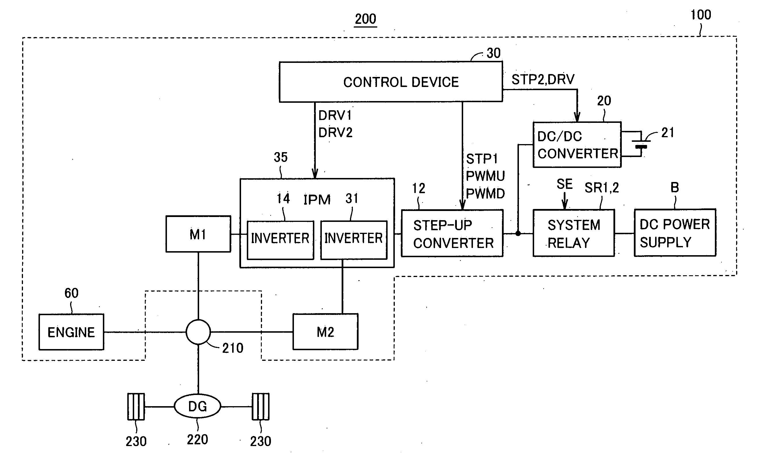
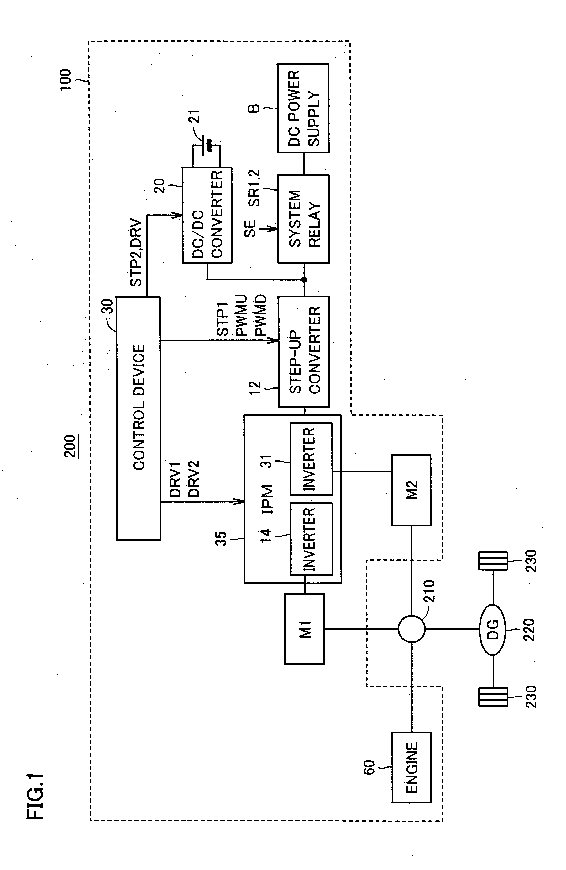
[0046]FIG. 1 is a schematic block diagram showing an exemplary hybrid vehicle equipped with a drive control apparatus for a rotating electric machine in accordance with an embodiment of the present invention.

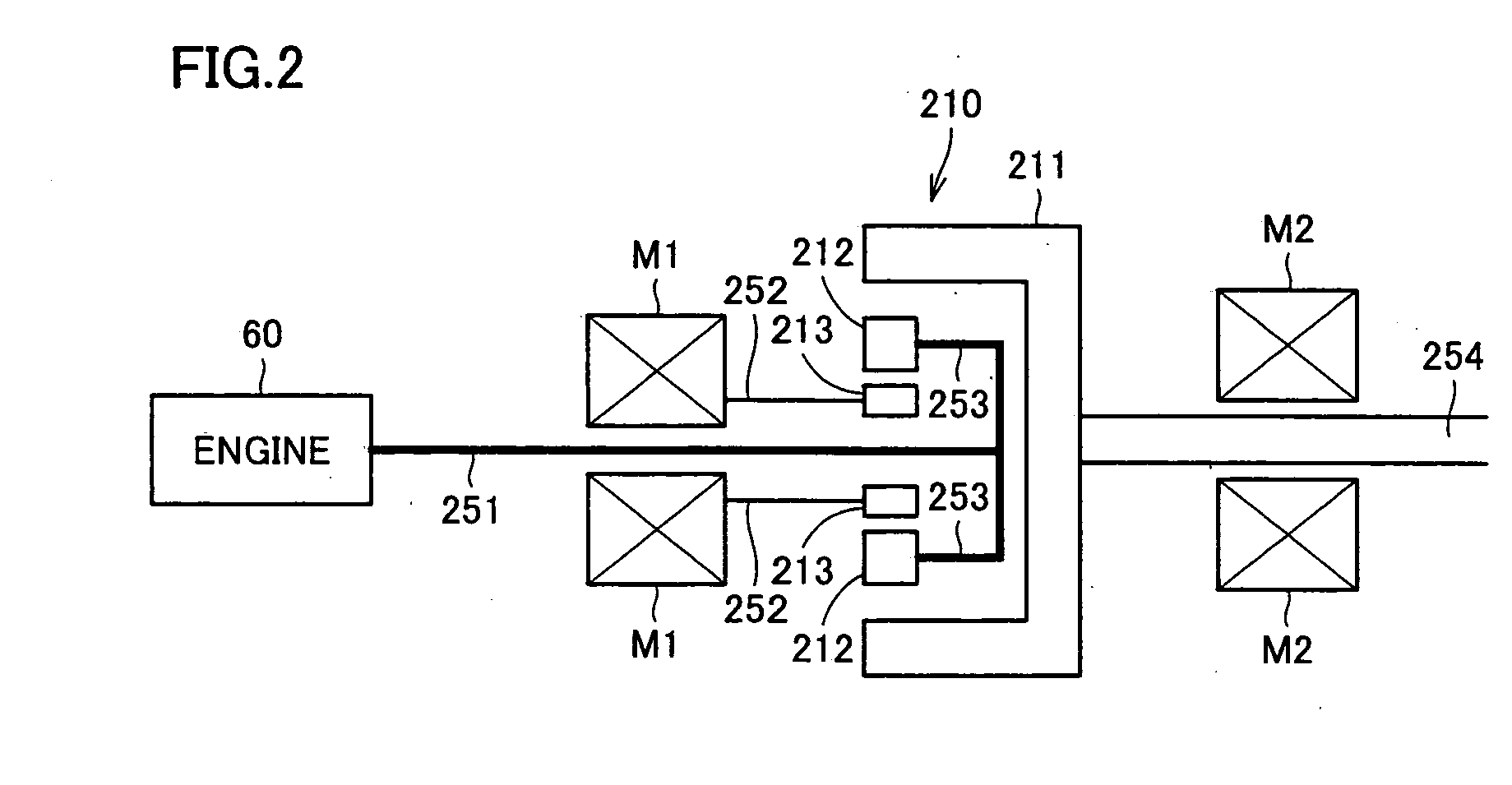
[0047]Referring to FIG. 1, a hybrid vehicle 200 includes a hybrid vehicle drive apparatus 100, a power split device 210, a differential gear (DG) 220, and front wheels 230. Hybrid vehicle drive apparatus 100 includes a DC power supply B, system relays SR1, SR2, a step-up converter 12, inverters 14, 31, a DC / DC converter 20, an auxiliary battery 21, a control device 30, an engine 60, and AC motors M1, M2. Inverters 14, 31 constitute an IPM (intelligent power module) 35.

[0048]AC mot...


PUM


Abstract

A drive control apparatus for an AC motor is mounted on a hybrid vehicle. The drive control apparatus includes an inverter for driving an AC motor, and a control device for controlling the inverter by switching a control mode of the inverter between a first mode and a second mode in which a harmonic component of output current of the inverter can be suppressed as compared with in the first mode. The control device controls the inverter in the first mode when a magnet temperature of a permanent magnet is smaller than a first threshold temperature, and controls the inverter in the second mode when a magnet temperature is equal to or larger than the first threshold temperature.

Description

TECHNICAL FIELD[0001]The present invention relates to a drive control apparatus for a rotating electric machine and a vehicle, and more particularly to a technique of preventing demagnetization of a permanent magnet included in a rotor in a permanent magnetic synchronous machine.BACKGROUND ART[0002]In recent years, electric powered vehicles such as hybrid vehicles and electric vehicles receive great attention as environmentally friendly cars. Such an electric powered vehicle includes a power storage device such as a secondary battery and a motor generator receiving electric power from the power storage device for generating a driving force. The motor generator generates a driving force at a time of starting or acceleration and also converts kinetic energy of the vehicle into electric energy for recovery into the power storage device at a time of braking.[0003]As a motor generator mounted on such an electric powered vehicle, a permanent magnetic synchronous machine is often used, bec...

Claims


Application Information

Patent Timeline
Patent Type & Authority Applications(United States)
IPC IPC(8): B60K6/48H02P6/10B60L50/16H02P6/06H02P6/08H02P6/12
CPCB60K1/02B60K6/365B60K6/445B60K6/547B60L2240/425B60L2260/167Y02T10/642B60W20/00B60W2510/087H02P6/10H02P29/0066Y02T10/6239B60W10/08B60W50/0097H02P29/662Y02T10/62Y02T10/64B60W2510/083B60W2510/104
Inventor TAKASAKI, AKIRA
Owner TOYOTA JIDOSHA KK
Why Eureka
Try Eureka