Fluid system coupling with pivoting handle actuating member

a technology of pivoting handle and pivoting handle, which is applied in the direction of couplings, pipe elements, sleeve/socket joints, etc., can solve the problems of wasting resources, difficulty in transporting fluid, and significant damage, and achieves convenient disengagement, facilitates secure engagement, and prevents intentional or accidental disengagement of the mating halves

Active Publication Date: 2010-01-21
HILTAP FITTINGS
View PDF71 Cites 6 Cited by
  • Summary
  • Abstract
  • Description
  • Claims
  • Application Information

AI Technical Summary

Benefits of technology

[0015]In general, embodiments of the invention are concerned with a fluid system component that, among other things, facilitates the secure engagement, and ready disengagement, of mating halves of the fluid system component, while at the same time preventing intentional or accidental disengagement of the mating halves when a predetermined pressure is present in the line.
[0016]In one exemplary embodiment of the invention, a fluid system component includes a coupling. The coupling itself can include a sleeve coupled to a pipe and a collar. The collar can include a collar handle and at least one engagement member that facilitate selective engagement of the collar with the sleeve. The collar can be rotated relative to the sleeve, in a first direction, thereby disengaging the engagement member from the groove. Disengagement of the engagement member from the groove can also disengage the collar from the sleeve and / or open the pipe. The sleeve and collar can be configured such that the engagement member fully disengages from the groove only when the pipe has a pressure below a certain level, and such that at or above that level, the engagement member is substantially prevented from fully disengaging from the groove. The collar can be coupled to the sleeve by positioning the engagement member within the groove and rotating the collar relative to the sleeve in a second direction that is opposite the first direction.
[0017]Optionally, the coupling includes a locking mechanism that prevents axial rotation of the collar relative to the sleeve. Such a locking mechanism can include a pin that extends through an aperture in the collar and / or is received within a recess in the sleeve. The pin and / or locking mechanism may also include a crank arm handle that facilitates retraction of the pin from the recess in the sleeve. The groove in the sleeve can be formed in an outer surface thereof, and can include an entry segment, a circumferential segment, and / or a terminal segment. In one example, the terminal segment is connected to the intermediate segment and is offset therefrom at an acute angle. The terminal segment may thus be adapted to receive an engagement member and prevent axial rotation of the collar relative to the sleeve.

Problems solved by technology

For example, it is very difficult to transport a fluid without spilling or leaking some of the fluid into the environment.
These environmental concerns become especially clear when considering the magnitude of the industries that handle hazardous fluids that, if allowed to escape even in relatively small quantities, can cause significant damage.
While some fluids that are transported, such as water and milk, may not significantly pollute the environment when they are leaked or spilled, the loss of fluid into the environment is nevertheless viewed as a general waste of resources.
More generally, the loss of fluid into the environment is not desirable even if the fluid does not contribute to pollution.
With each transfer of fluid, there is a risk that leakage will occur due to human error, equipment malfunctions, or the like.
A common source of fluid leaks and fluid spills are the valves and other components and devices employed in fluid systems.
By way of example, some valves may have leaks that permit flow through the valve even when the valve is secured in the closed position.
In other instances, one or more joints defined by constituent elements of the valve, such as in the case of valves designed to be taken down in two or more pieces, and / or one or more joints at least partially defined by the valve, such as a valve-to-flange connection, may be defective, resulting in leakage of some or all of the system fluid.
Unfortunately, problems such as these often do not manifest themselves until after flow has been established through the valve, component, or device.
Thus, in many instances, the system operator is limited in terms of the affirmative steps that can be taken to prevent a spill that may result from one or more defective joints, and oftentimes can only correct the spill when it occurs.
This is true in the case of joints that are defectively assembled, or are otherwise defective upon assembly, as well as in the case of joints that become defective over a period of time due to operating, or other, conditions.
Such an arrangement is problematic for a variety of reasons.
By way of example, in the event the line wherein the quick coupling device is located is charged with hazardous materials such as chemicals, sewage, fuels, or gases such as chlorine and methane, the operator performing the uncoupling operation could be seriously injured or killed when such materials escape from the line.
Moreover, such hazardous materials are pollutants and significant time and cost is often involved in the cleanup of such materials.
A related problem with typical quick coupling devices concerns the pressure exerted by the material in the line wherein the quick coupling device is located.
In particular, such pressure may cause the halves of the quick coupling device to rapidly come apart in an uncontrolled and dangerous manner, thereby injuring the operator and / or damaging nearby equipment.
The forces resulting from such pressure can often be significant, even where the line pressure is relatively low.
Not only are such pressures dangerous, but operators may not have any way to verify, in advance of performing the uncoupling operation, whether or not the line is pressurized.
Further, even if an operator is aware that pressure is present, the operator may, through inattentiveness, negligence, or for other reasons, nevertheless attempt to uncouple the quick coupling device.
Additionally, fluid system components are often exposed to extreme temperatures, either from the environment or the fluid flowing through the fluid system.
The extreme temperatures can cause the various fluid system components to expand or contract.
Thus as a first component expands or contracts at one rate, and a second component expands or contracts at a another rate, the two components may become frictionally locked together, thereby making it difficult to disengage one component from another.

Method used


Image

  • Fluid system coupling with pivoting handle actuating member
  • Fluid system coupling with pivoting handle actuating member
  • Fluid system coupling with pivoting handle actuating member

Examples


Embodiment Construction

[0040]Reference will now be made to figures wherein like structures will be provided with like reference designations. It is to be understood that the drawings are diagrammatic and schematic representations of various embodiments of the invention, and are not to be construed as limiting the present invention, nor are the drawings necessarily drawn to scale.

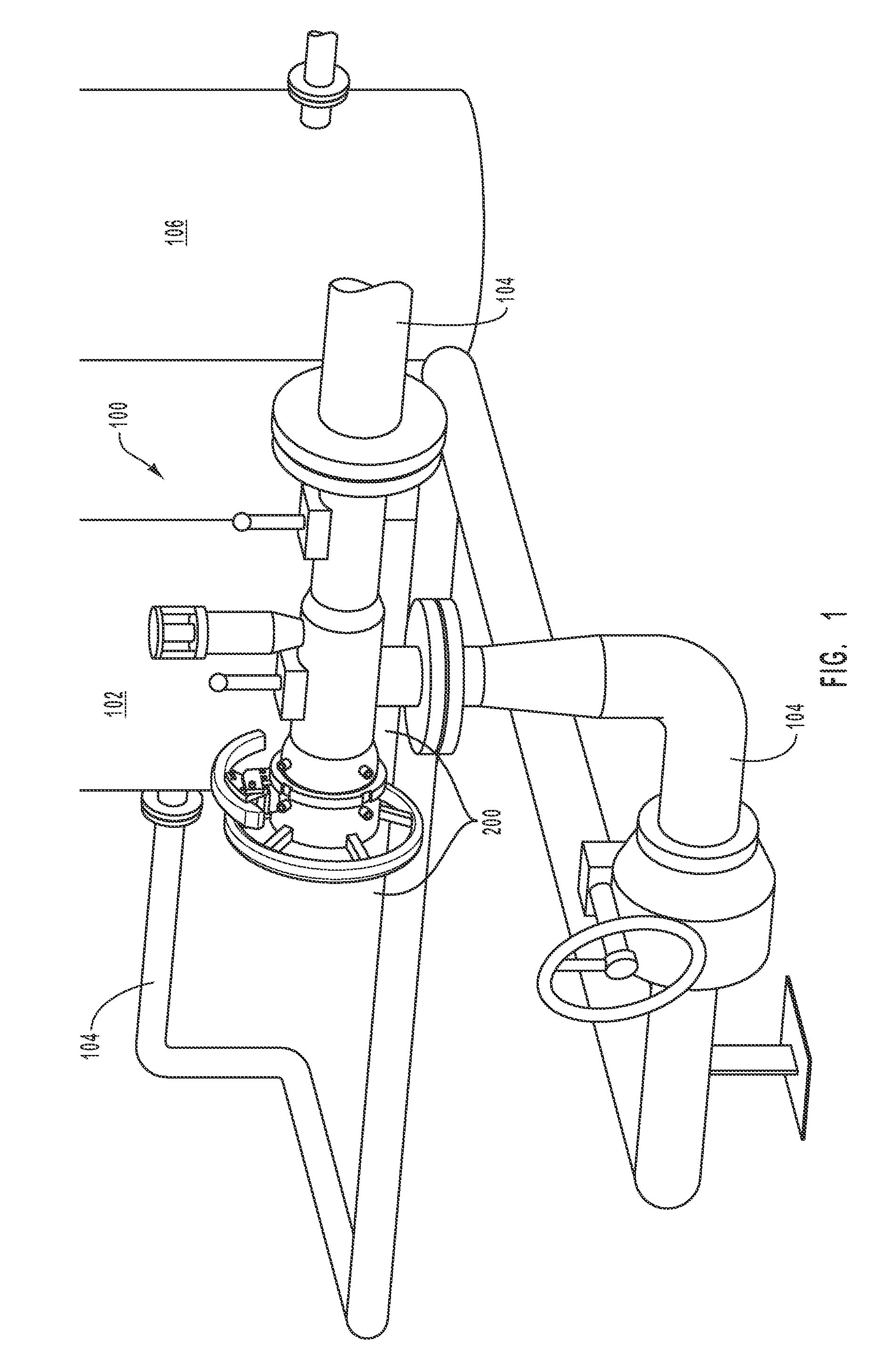
[0041]With reference first to FIG. 1, a portion of one embodiment of a fluid system is indicated generally at 100. Note that, as contemplated herein, “fluid” is not limited to liquids, but can include a variety of other compositions. For example, the term “fluid,” as used herein, expressly includes liquids, gases, liquid-gas combinations, slurries, liquid-solid combinations, gas-solid combinations, and liquid-solid-gas combinations. In the exemplary embodiment depicted in FIG. 1, fluid system 100 includes a fluid source 102 in fluid communication with one or more fluid conduits 104. According to some example embodiments at least o...


PUM


Abstract

A fluid system component is provided that includes first and second elements configured to be removably engaged with each other to define a fluid passageway. The first element defines at least one groove. Correspondingly, the second element includes at least one engagement member configured to be received in a corresponding groove. The presence of a line pressure in the passageway substantially forecloses disengagement of the first and second elements until the fluid pressure in the fluid passageway has decreased to a predetermined magnitude. A handling and locking mechanism for selectively securing the second element relative to the first element is included. The locking mechanism includes a pin controlled by a crank arm assembly adjacent a collar handle. The crank arm assembly includes a crank arm handle that rotates to withdrawn the pin from the second element and which facilitates rotation of the first element relative to the second element.

Description

BACKGROUND[0001]1. Technical Field[0002]The present invention relates generally to fluid system components. More particularly, embodiments of the present invention relate to coupling elements for fluid system components, in which the coupling elements facilitate quick and efficient coupling / decoupling of the fluid system components. Further, embodiments of the present invention relate to fluid system components which substantially prevent unintentional removal of a coupling element until the fluid system line pressure, or relative pressure differential, is reduced to a safe level.[0003]2. Related Technology[0004]In recent years, environmental concerns have been receiving significantly more attention, and various governmental agencies have responded by implementing stringent regulations to reduce or prevent pollution. Many of these regulations and concerns are directed towards those industries that transport fluids. For example, it is very difficult to transport a fluid without spill...

Claims


Application Information

Patent Timeline
Patent Type & Authority Applications(United States)
IPC IPC(8): F16L37/107
CPCF16L2201/10F16L37/113
Inventor KRYWITSKY, LEE A.
Owner HILTAP FITTINGS
Why Eureka
Try Eureka