Aircraft combination engines plural airflow conveyances system

a technology of airflow conveyancing system and aircraft combination engine, which is applied in the direction of reciprocating combination engine, engine starter, electric generator control, etc., can solve the problems of large electrical power demand peaks repeatedly, low fuel use efficiency during flight, and high electrical power demand

Inactive Publication Date: 2010-01-21
UNITED TECH CORP
View PDF3 Cites 16 Cited by
  • Summary
  • Abstract
  • Description
  • Claims
  • Application Information

AI Technical Summary

Benefits of technology

[0010]The present invention provides an engine combination for generating forces with a gas turbine engine having an air inlet open to the atmosphere, an air compressor, a combustor, a turbine and an exhaust exit nozzle open to the atmosphere positioned along a fluids flow path passing through all for generating force with the gas turbine engine having a plurality of air transfer ducts each extending from a different location therein so as to be capable to provide air in each of those air transfer ducts at one end thereof at pressures differing from one another. In addition, an internal combustion engine is provided in the combination as an intermittent combustion engine having an air intake coupled to combustion chambers therein and a rotatable output shaft for generating force also coupled to those combustion chambers, the plurality of air transfer ducts each being connected at an opposite end thereof to the air intake to be capable of being selected to transfer air thereto. A plurality of control valves can be provided each at least provided partially in a corresponding one of the plurality of air transfer ducts at least some of which control valves can be selectively directed to open more or close more to thereby selectively affect the passage of air through that air duct. A primary electrical generator having an output conductor can have a rotatable input shaft connected to the intermittent combustion engine output shaft with the output conductor being electrically energized in response to rotation of the input shaft.

Problems solved by technology

Furthermore, such demands for electrical power in military aircraft often occur at relatively high altitudes and often occur unevenly over relatively long time durations of use, that is, large peaks repeatedly occur in electrical power demand in the course of those long use durations.
Making up that thrust loss in these circumstances by operating such available turbine engines so as to increase the thrust output thereof causes the already relatively low fuel use efficiency during flight to decrease significantly, which can severely limit the length of otherwise long duration uses, and also brings those engines closer to becoming operationally unstable.
At high altitudes, internal combustion engines of all kinds face the possibility of limited power output because of the relatively small air pressures there limiting the chemical reactions of oxygen with hydrogen and oxygen with carbon in the burning of the engine fuel in the engine combustion chamber or chambers.
In other circumstances, difficulties arise because of aircraft operations being required at different altitudes with the attendant different air pressures, because of different gross weights due to different flight missions and the consumption of fuel during flights with the attendant differing operating powers that must be provided by the gas turbine engine, and the like.
In these other circumstances, the intermittent combustion engine might be overpressured at its air intake because the compression ratio of the engine could increase the pressure of the already compressed air supplied thereto to the point of some containment component bursting.
Alternatively, the intermittent combustion engine might be insufficiently pressured there to result in incomplete combustion in the combustion chambers thereof and so a reduced output torque.

Method used


Image

  • Aircraft combination engines plural airflow conveyances system
  • Aircraft combination engines plural airflow conveyances system

Examples


Embodiment Construction

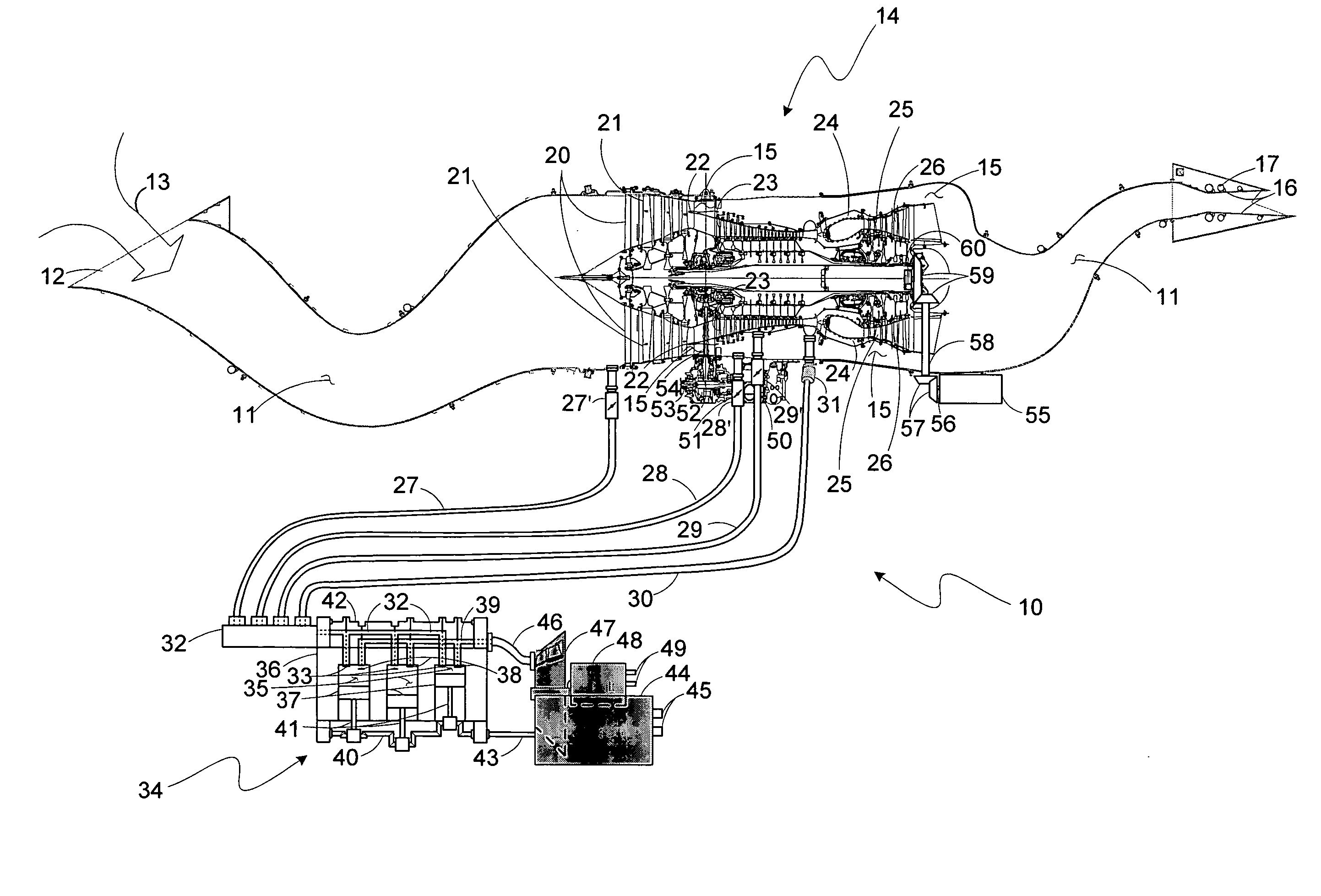
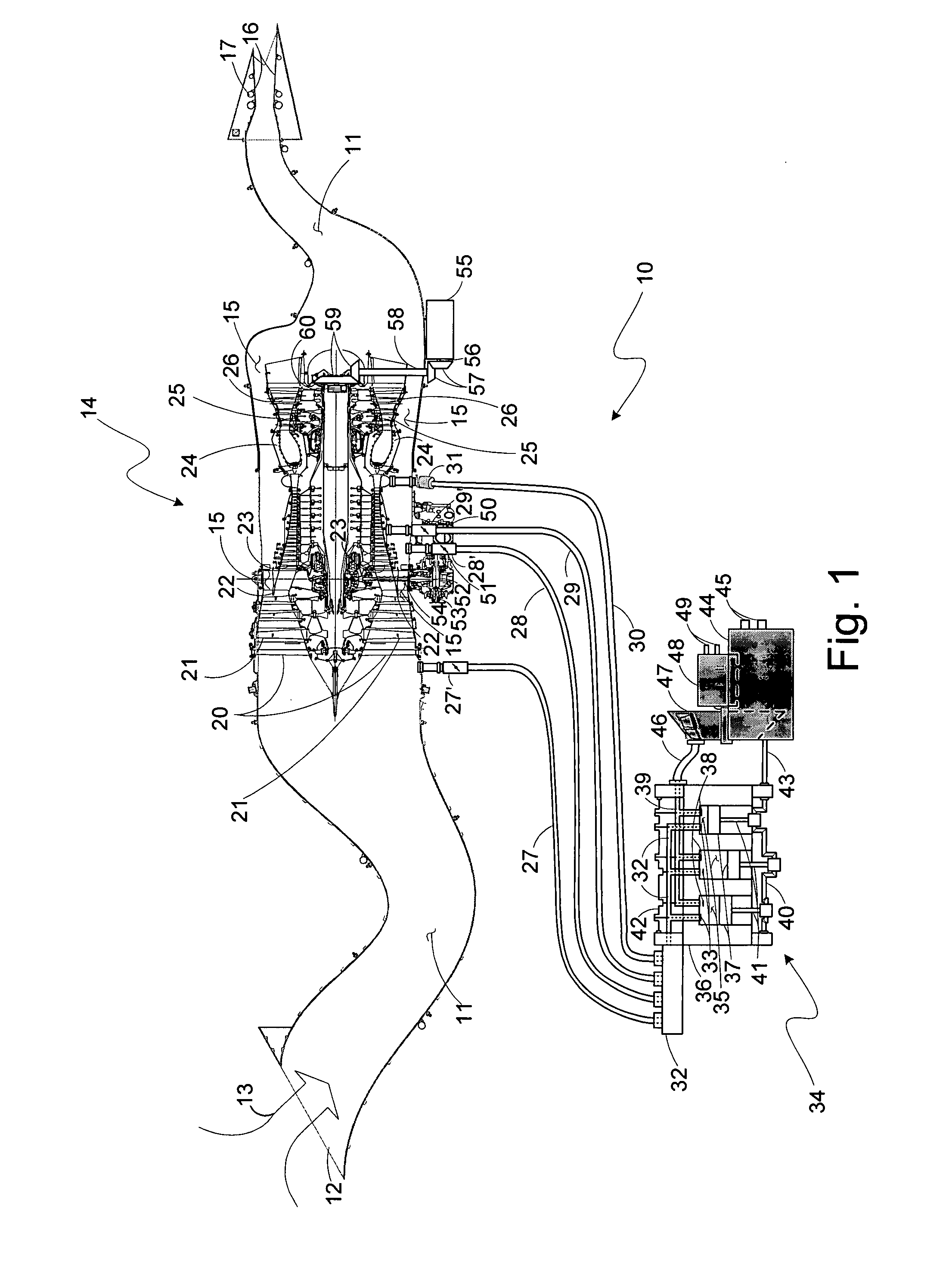
[0012]A larger range of optimum, or near optimum, of pressures of the air supplied to the air intake of the intermittent combustion engine, during its operation over a variety of aircraft flight conditions and aircraft electrical power electrical power demands, can be provided by conveying air to that intake from different locations in the gas turbine engine at each of which the local air pressure differs from that of the others. As an example, a turbofan engine provides airstreams therethrough with differing air pressures at different locations along the stream as well as different airstreams each at air pressures differing from that of the other or others, and these differences occur over a large range of pressures from atmospheric at the engine air inlet to many times that pressure at the output location of the high compression air compressor.

[0013]The availability of these alternative airstreams, along with some range of pressure regulation of the air drawn therefrom, allows cho...


PUM


Abstract

An engine combination for generating forces with a gas turbine engine generating force, and an internal combustion engine provided in the combination as an intermittent combustion engine generating force having an air intake, there being a plurality of air transfer ducts each extending from a different location in the gas turbine engine so as to be capable to provide air in each of those air transfer ducts at one end thereof at pressures differing from one another and connected at the other end of each to the air intake to transfer air thereto.

Description

CROSS-REFERENCE TO RELATED APPLICATION[0001]Referenced herein is U.S. application Ser. No. 11 / 713,262 filed Mar. 2, 2007 for “COMBINATION ENGINES FOR AIRCRAFT” by Frederick M. Schwarz, Brian M. Fentress, Andrew P. Berryann, Charles E. Lents and Jorn A. Glahn.BACKGROUND OF THE INVENTION[0002]The present invention relates to gas turbine engines for aircraft and, more particularly, to gas turbine engines each coupled to a corresponding auxiliary engine.[0003]Gas turbine engines as continuous combustion, open Brayton cycle internal combustion engines have come to dominate as the power plants for larger, faster aircraft to essentially the exclusion of reciprocating engines, or internal, intermittent combustion engines, earlier used as power plants for these kinds of aircraft. This is largely because of the greater power-to-weight ratio of gas turbine engines versus internal combustion engines, especially in large horsepower engines, or, more appropriately, large thrust engines in which t...

Claims


Application Information

Patent Timeline
Patent Type & Authority Applications(United States)
IPC IPC(8): F01B21/04H02K23/52F01D15/10
CPCF01D13/02F05D2220/76F02C5/06F02C6/08
Inventor SCHWARZ, FREDERICK M.FENTRESS, BRIAN M.
Owner UNITED TECH CORP
Why Eureka
Try Eureka