Eureka AIR delivers breakthrough ideas for toughest innovation challenges, trusted by R&D personnel around the world.

Apparatus and method for detecting decrease in tire air pressure and program for detecting decrease in tire air pressure.

Active Publication Date: 2010-01-21
SUMITOMO RUBBER IND LTD
View PDF1 Cites 24 Cited by
  • Summary
  • Abstract
  • Description
  • Claims
  • Application Information

AI Technical Summary

Benefits of technology

[0016]The present invention has been made in view of the situation as described above. It is an objective of the present invention to provide an apparatus and a method for detecting a decrease in a tire air pressure by which the estimation accuracy regarding a resonance frequency of a wheel rotation signal can be increased, and a program for detecting a decrease in a tire air pressure.

Problems solved by technology

If the air pressure value decreases and is lower than an appropriate value, this may cause deteriorated operation stability and fuel efficiency to consequently cause a tire burst.
The direct TPMS can accurately detect a decrease in a tire air pressure but requires an exclusive wheel and has a poor fault-tolerance performance in an actual environment for example.
Thus, the direct TPMS has disadvantages in technique and cost.
However, this DLR method merely makes a relative comparison among wheel rotation velocities and thus cannot sense a case of four tire simultaneous deflation (natural leakage).
Furthermore, this DLR method also has a disadvantage in that this method cannot accurately sense a reduced pressure in all vehicle running statuses because a difference in the wheel speed is also caused by running conditions such as a vehicle turning, acceleration and deceleration, or an uneven load.
However, the RFM method is disadvantageous in that some running condition causes a strong noise for example and thus an estimated frequency value in a target domain is not robust enough with regard to a vehicle speed or a road surface condition for example.
Thus, this RFM method focuses on this resonance frequency and issues an alarm when it is determined that the frequency is relatively lower than a reference frequency estimated during initialization.
However, an in-vehicle calculator having a limited computational resource has a difficulty in storing required time-series data, thus making it difficult to carry out the FFT frequency analysis.
However, many conventionally-suggested methods have disadvantages as described below.
Specifically, a signal noise (SN) ratio is consequently poor and thus an accurate estimation of the resonance frequency is difficult.
Secondly, when the vehicle is running at a high speed (80 km or more per hour), causing factors such as an increase in the up-and-down vibration of the tires cause a stronger signal having a high frequency component, thus causing a tendency where the resonance peak is unclear.
Thirdly, when a strong noise has a peak in the vicinity of a frequency domain having a resonance peak, the influence by this noise causes an unstable estimated resonance frequency value. FIG. 9 shows the result obtained by applying FFT to the running data obtained under the circumstance as described above.
Some running condition causes these problems to be superimposed, thus making it particularly difficult to estimate a resonance frequency in a stable manner.
Furthermore, an unstable estimated value also makes it difficult to set a reference value for determining abnormality, which is a causing factor that makes it difficult to put an abnormality detection system based on the RFM method into practical use.
Initialization of all of these 27 windows is not only complicated but also causes a case where a not-yet-initialized window cannot be subjected to the determination of abnormality.
However, since the interpolation method is not based on a tire physical characteristic, the abnormality detection accuracy has a poor reliability.
Thus, the abnormality detection has a problematic universality.

Method used


Image

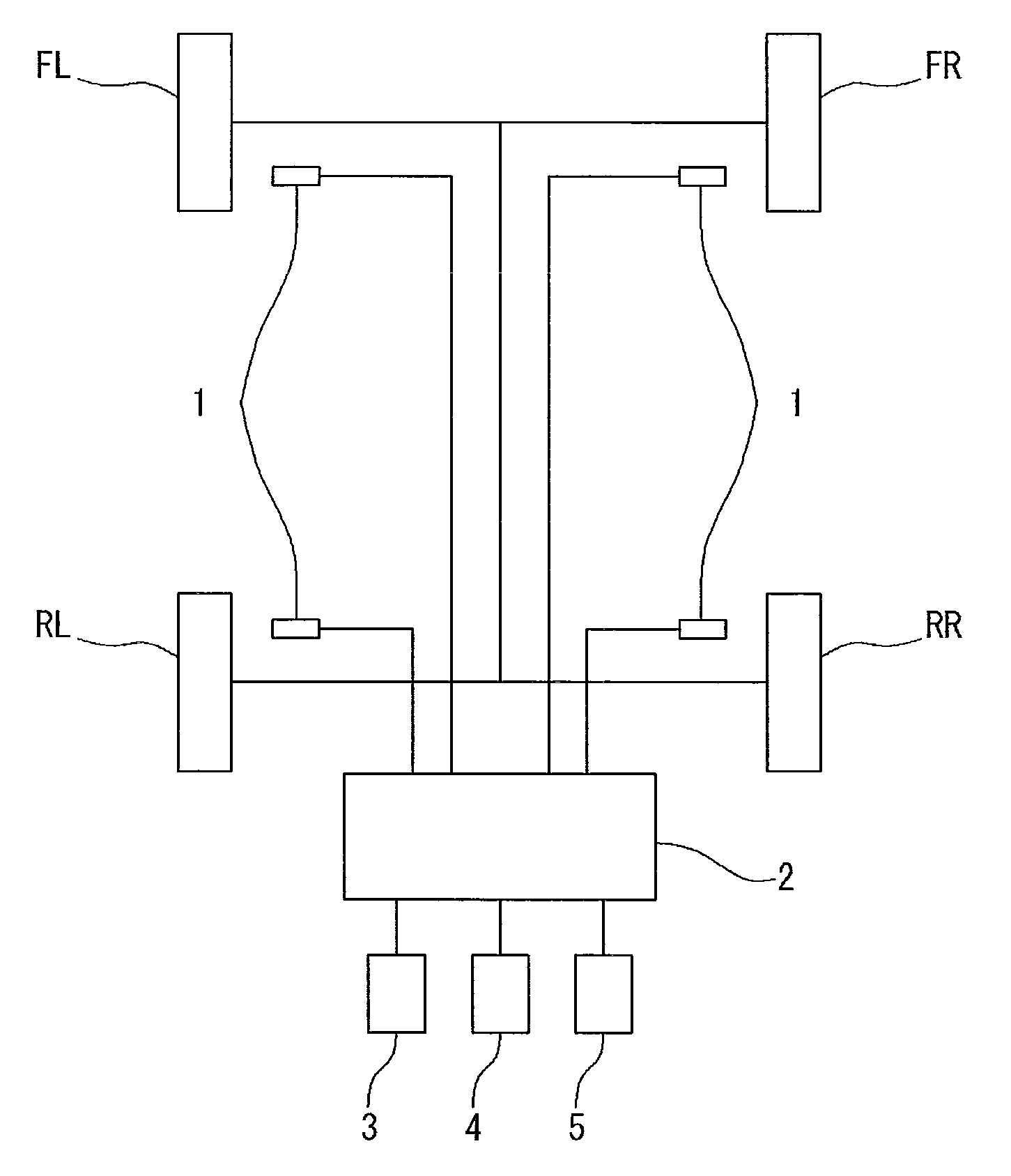
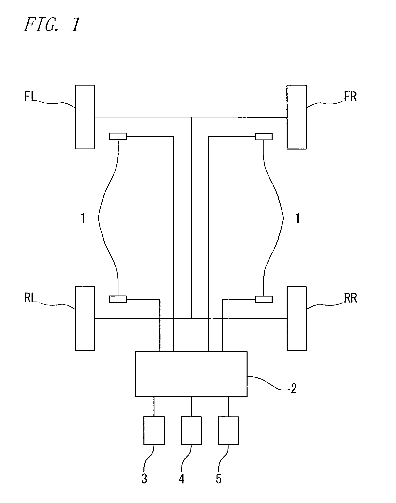
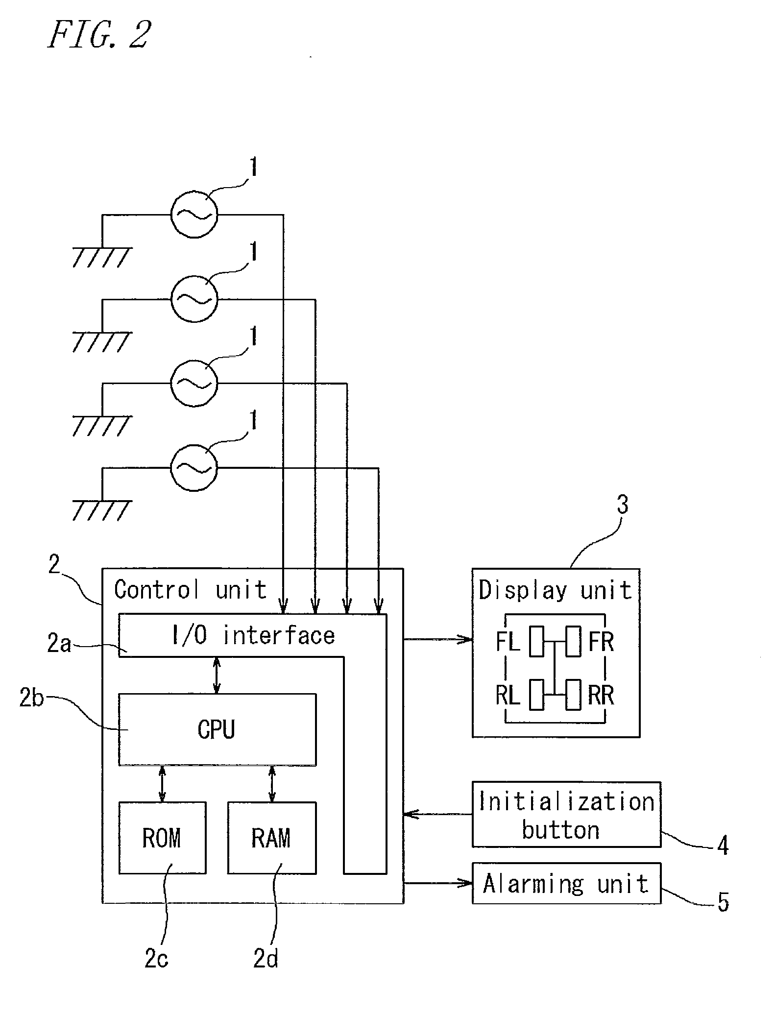
  • Apparatus and method for detecting decrease in tire air pressure and program for detecting decrease in tire air pressure.
  • Apparatus and method for detecting decrease in tire air pressure and program for detecting decrease in tire air pressure.
  • Apparatus and method for detecting decrease in tire air pressure and program for detecting decrease in tire air pressure.

Examples


example

[0091]Next, an example of the detection method of the present invention will be described. However, the present invention is not limited to the following example only.

[0092]Runflat tires (size: 245 / 40R18) were attached to a four-wheel-drive vehicle of 2800 cc displacement. Then, the vehicle was made to run and the rotation information regarding the respective tire wheels was sampled at every 4 ms to obtain the time-series data for the wheel speed signal. Then, a time difference among the resultant wheel speeds was calculated to thereby obtain a wheel acceleration. The following four running conditions were used.

[0093](a) Running on a road having a significantly-uneven road surface at a low speed (50 km per hour)

[0094](b) Running on a road having a smooth road surface at a low speed (50 km per hour)

[0095](c) Running on a road having a significantly-uneven road surface at a high speed (100 km per hour)

[0096](d) Running on a road having a smooth road surface at a high speed (100 km per...


PUM


Abstract

An apparatus for detecting a decrease in a tire air pressure includes; a rotation velocity information detection means for regularly detecting tire rotation velocity information regarding the respective wheels of a vehicle; a resonance frequency estimation means for estimating a resonance frequency of the rotation velocity information based on the rotation velocity information obtained by the rotation velocity information detection means; and a determination means for determining, based on the estimated resonance frequency, a decrease in the tire air pressure. The apparatus includes a data rejecting means for rejecting data of rotation velocity information hindering the estimation of the resonance frequency.

Description

BACKGROUND OF THE INVENTION[0001]1. Field of the Invention[0002]The present invention relates to an apparatus and a method for detecting a decrease in a tire air pressure of a running vehicle based on the resonance frequency of the tire as well as a program for detecting a decrease in a tire air pressure.[0003]2. Description of the Related Art[0004]Factors for enabling the safe running of an automobile include a tire air pressure. If the air pressure value decreases and is lower than an appropriate value, this may cause deteriorated operation stability and fuel efficiency to consequently cause a tire burst. To prevent this, a tire air pressure alarming apparatus (Tire Pressure Monitoring System; TPMS), which is to detect the decrease in a tire air pressure to notify a driver of this decrease to prompt the driver to take an appropriate measure, is an important technique from the viewpoints of environment conservation and the secured safety of the driver.[0005]A conventional alarming ...

Claims


Application Information

Patent Timeline
IPC IPC(8): B60C23/00
CPCB60C23/062B60C23/061
Inventor FUJITA, HAJIMEKAWASAKI
Owner SUMITOMO RUBBER IND LTD
Why Eureka
Eureka Blog
Learn More