Device for monitoring breathing during sleep and ramped control of CPAP treatment
Inactive Publication Date: 2002-01-17
RESMED LTD
View PDF0 Cites 56 Cited by
Summary
Abstract
Description
Claims
Application Information
AI Technical Summary
This helps you quickly interpret patents by identifying the three key elements:
Problems solved by technology
Method used
Benefits of technology
0054] FIG. 13 shows an example of how the pressure wave generated by snoring progressively inc
Problems solved by technology
Obstructive sleep apnea sufferers repeatedly choke on their tongue and soft palate throughout an entire sleep period resulting in lowered arterial blood oxygen levels and poor quality of sleep.
Thus the appropriate pressure found in the laboratory is necessarily the maximum of all these minimum pressures for that particular night and is not necessarily the ideal pressure for all occasions nor for every night.
However, the prior art provides no facility to take advantage of this fact other than by regular diagnostic sleep periods in a sleep clinic or hospital.
When a patient undergoing CPAP opens his mouth with pressurized air being forced through the nose the pressured air exits out of the mouth producing an unpleasant sensation.
This can occur when the patient puts on the mask connected to the pressured air supply before falling asleep and some patients will therefore leave the mask off for as long as possible and may in fact fall asleep without wearing the mask and therefore without the benefits of the CPAP therapy.
In addition to the problems associated with administering CPAP therapy there exists the inconvenience and cost of diagnosis which is currently undertaken by overnight observation at a sleep clinic
Method used
Image
Click on the blue label to locate the original text in one second.
Reading with bidirectional positioning of images and text.
Examples
Embodiment Construction
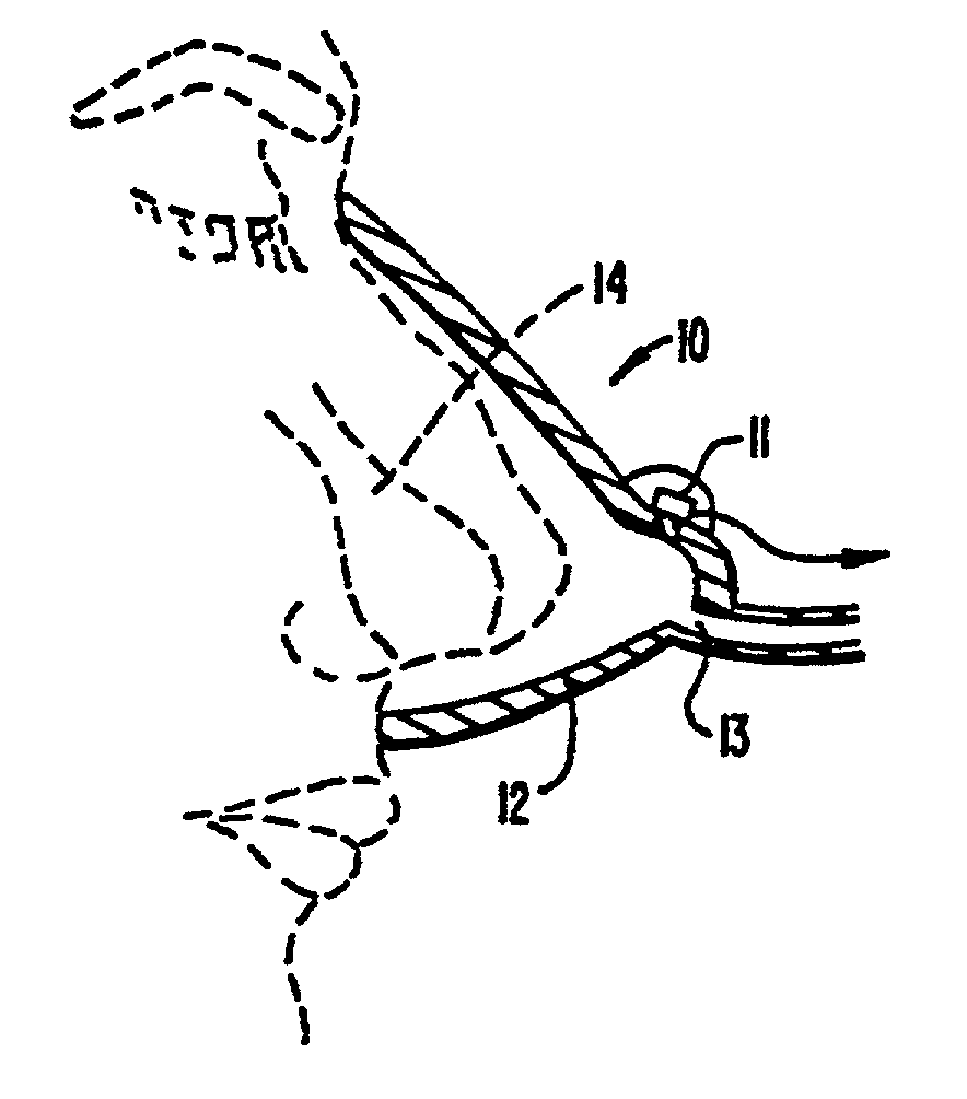
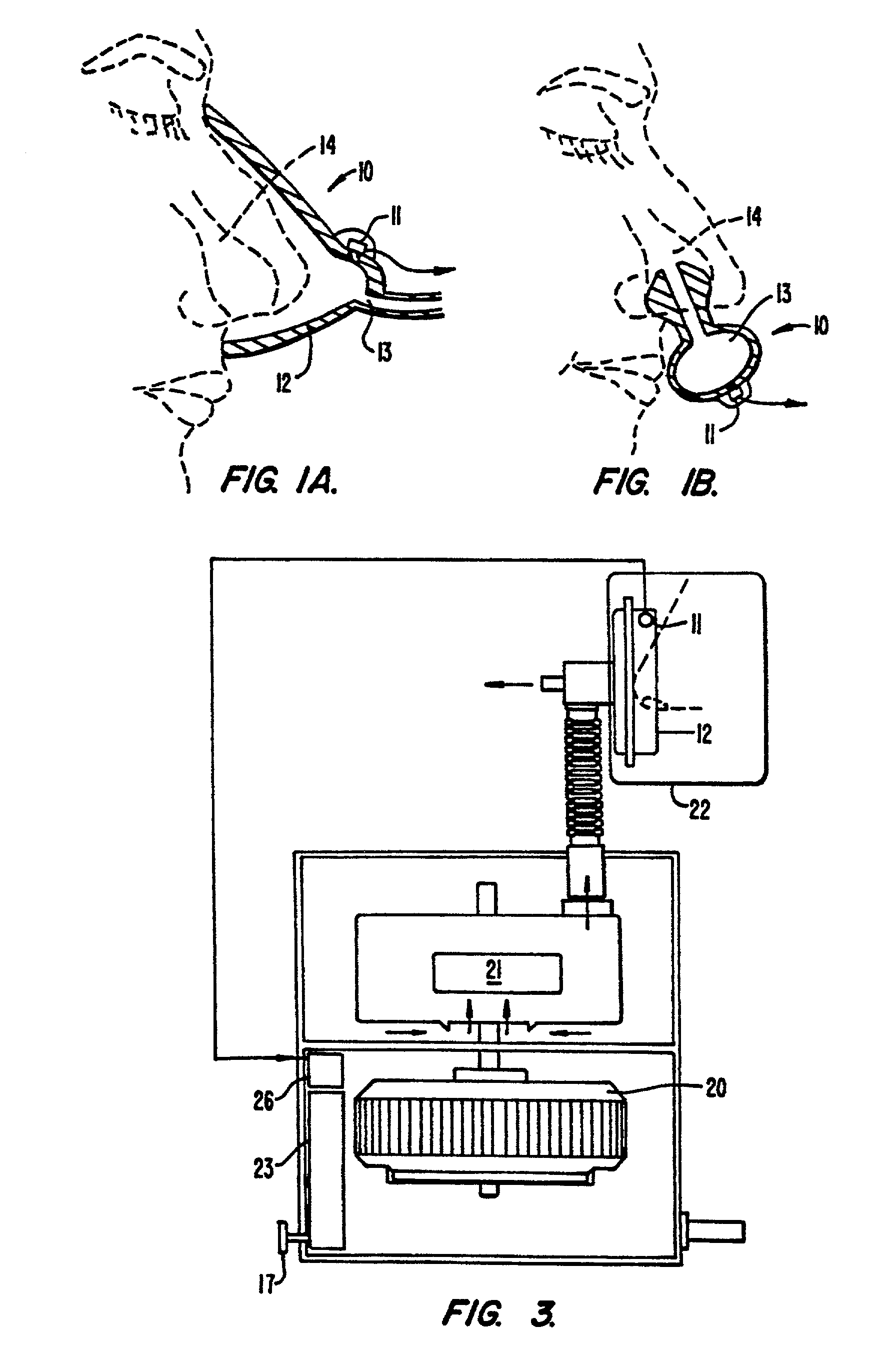
[0055] FIG. 1a illustrates a snoring detection device 10 comprising a microphone 11, in sound communication with the container 12 of a nose mask. Air, being inhaled by the patient, enters the nasal passageways 14 through the opening 13 in the nose mask 12 and is exhaled in the reverse direction. As the airway extends from the source of snoring sounds within the patient's body, through the nasal passages 14 and out of the opening 13 in the nasal mask, the microphone 11 is ideally located to take advantage of the natural stethoscope formed by the enclosed airway. Hence the snoring and breathing sounds are focused and concentrated by this arrangement. Alternatively, the microphone 11 may be located within, or attached externally of, a nasal prong device as illustrated in FIG. 1b. The detection device 10 can be used in a diagnostic device or a feedback control. In the case of the detection device 10 being used in diagnostic equipment there is connected to the microphone 11 an electronic...
PUM
Abstract
A CPAP apparatus including: a variable pressured air source and means to vary the air pressure delivered therefrom; a nose piece for sealed air communication with a patient's respiratory system; an air communication line from the air source to the nose piece; a sound transducer adapted to be in sound communication with the patient's respiratory system; and a feedback system controlling the output pressure of the air source in response to an output from the transducer so as to increase the output air pressure from said air source, in response to detection of sound indicative of snoring, in accordance with a predefined procedure. The sound transducer, in its most general form, comprises a pressure transducer which, in addition to detecting snoring sounds, can detect other respiratory parameters such as the rate of breathing, inhaled air flow volume, and inhaled air flow rate. Output air pressure from air source is increased in response to one or more of these parameters in accordance with a pre-defined procedure.
Description
[0001] This is a continuation of U.S. application Ser. No. 09 / 365,643, filed on Aug. 2, 1999, pending, which is a continuation of U.S. application Ser. No. 08 / 934,176, filed on Sep. 19, 1997, now abandoned, which is a continuation of U.S. application Ser. No. 08 / 838,462, filed on Apr. 7, 1997, now abandoned, which is a continuation of U.S. application Ser. No. 08 / 654,742, filed on May 29, 1996, now abandoned, which is a continuation of U.S. application Ser. No. 08 / 385,742, filed on Feb. 8, 1995, now abandoned, which is a continuation of U.S. application Ser. No. 08 / 100,556, filed Jul. 30, 1993, now abandoned, which is a divisional of U.S. application Ser. No. 07 / 892,692, filed May. 27, 1992, now U.S. Pat. No. 5,245,995, which is a continuation of U.S. application Ser. No. 07 / 548,108, filed Jul. 5, 1990, now abandoned, which is a continuation-in-part of U.S. application Ser. No. 07 / 457,757 filed Dec. 21, 1989, now abandoned, which was the National Stage for International Application ...
Claims
Application Information
Patent Timeline
Application Date:The date an application was filed.
Publication Date:The date a patent or application was officially published.
First Publication Date:The earliest publication date of a patent with the same application number.
Issue Date:Publication date of the patent grant document.
PCT Entry Date:The Entry date of PCT National Phase.
Estimated Expiry Date:The statutory expiry date of a patent right according to the Patent Law, and it is the longest term of protection that the patent right can achieve without the termination of the patent right due to other reasons(Term extension factor has been taken into account ).
Invalid Date:Actual expiry date is based on effective date or publication date of legal transaction data of invalid patent.