
In-vivo sensing device and method for communicating between imagers and processor thereof

a sensing device and in-vivo technology, applied in the field of in-vivo sensing devices, can solve the problems of increasing reducing the room occupied by the conducting line, and reducing the power consumption so as to reduce the complexity of the associated electrical circuit and the power consumption

Inactive Publication Date: 2010-01-21
GIVEN IMAGING LTD
View PDF64 Cites 52 Cited by
  • Summary
  • Abstract
  • Description
  • Claims
  • Application Information

AI Technical Summary

Benefits of technology

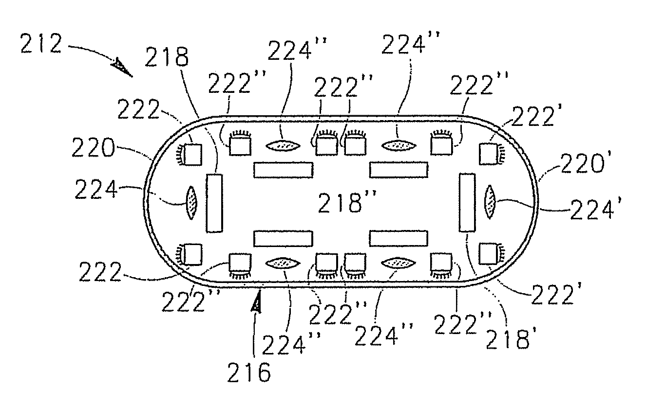
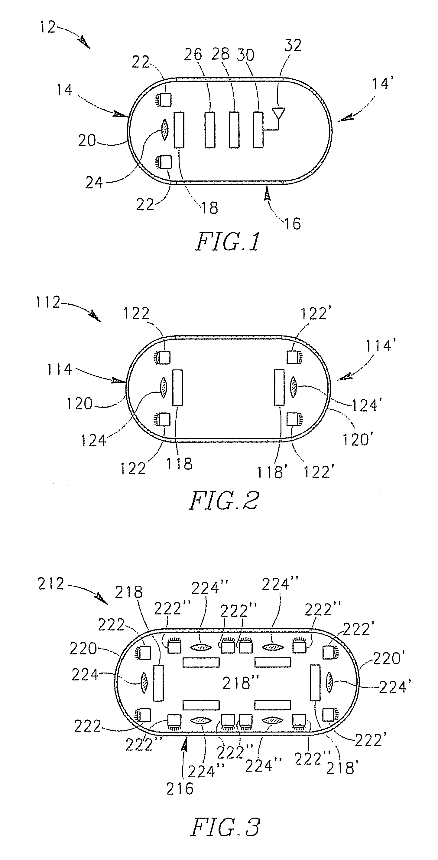
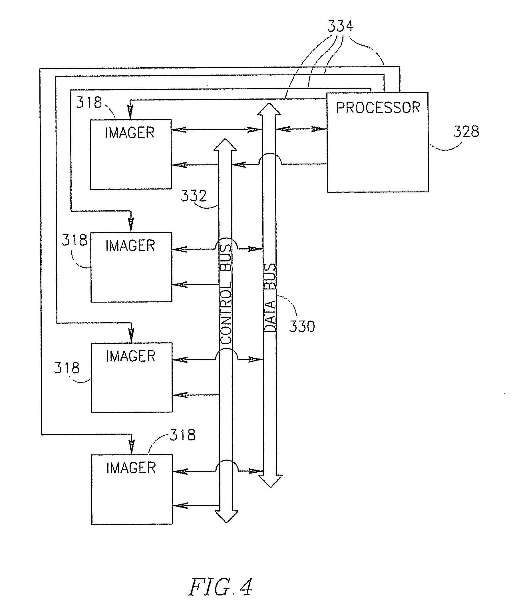
[0006]There is provided, in accordance with some embodiments of the present invention, an in-vivo imaging device having a plurality of imagers controlled by a single processor. There is also provided, in accordance with some embodiments of the present invention, a method for communicating between the processor and the imagers. The processor and imagers are electrically connected via a common data bus and a common control bus, instead of by direct separate conducting lines thereby reducing the number of pins on the processor and the corresponding number of conducting lines. Consequently, in comparison to direct electrical connection of the processor and imagers, there is a decrease in the room occupied by the conducting lines, a decrease in power usage and a decrease in the level of complexity of the associated electrical circuit.
[0009]Each imager may be connected to the processor with a separate reset line. The system may further comprise certain elements such as a power source or a clock signal source, which may have to be stabilized before the imagers start working. The processor may initiate the imagers at the right moment after all the elements are stabilized using the separate reset lines. A separate reset line may facilitate easy initialization of a specific imager. A separate reset line may enable easy activation of a specific idle imager, and may facilitate easy synchronization of the imagers among themselves and with the processor. A separate reset line may enable individual communication with specific imagers. In accordance with some embodiments, a single reset line may connect between all the imagers and the processor. In such embodiments, all the imagers may be reset simultaneously. In accordance with some embodiments, reset may also be performed through the common control bus by a command which is addressed to a specific imager using the unique identity information of that imager.

Problems solved by technology

Consequently, in comparison to direct electrical connection of the processor and imagers, there is a decrease in the room occupied by the conducting lines, a decrease in power usage and a decrease in the level of complexity of the associated electrical circuit.

Method used


Image

  • In-vivo sensing device and method for communicating between imagers and processor thereof
  • In-vivo sensing device and method for communicating between imagers and processor thereof
  • In-vivo sensing device and method for communicating between imagers and processor thereof

Examples


Embodiment Construction

[0023]The following description is presented to enable one of ordinary skill in the art to make and use the invention as provided in the context of a particular application and its requirements Various modifications to the described embodiments will be apparent to those with skill in the art and the general principles defined herein may be applied to other embodiments. Therefore, the present invention is not intended to be limited to the particular embodiments shown and described, but is to be accorded the widest scope consistent with the principles and novel features herein disclosed. In the following detailed description, numerous specific details are set forth in order to provide a thorough understanding of the present invention. However, it will be understood by those skilled in the art that the present invention may be practiced without these specific details. In other instances, well-known methods, procedures, and components have not been described in detail so as not to obscu...


PUM


Abstract

An in-vivo sensing device having multiple imagers controlled by a single processor and a method for communicating between the processor and the imagers. The processor and imagers are connected via common data and control busses, instead of by direct separate conducting lines thereby reducing the number of pins on the processor and the corresponding number of conducting lines.

Description

FIELD OF THE INVENTION[0001]The present invention relates to an in-vivo sensing device having a plurality of imagers controlled by a single processor and a method for communicating between the processor and the imagers.BACKGROUND OF THE INVENTION[0002]In-vivo devices, such as, for example, swallowable capsules, may be capable of gathering information regarding a body lumen while inside the body lumen. Such information may be, for example, a stream of images of the body lumen and / or measurements of parameters that are of medical concern, such as, for example, pH.[0003]In an in-vivo sensing device having a single imager, the imager may receive input data in the form of control commands or instructions from a processor and in return may transmit sensed data, such as image data, to the processor. Data may be transferred between the imager and processor via input and output ports, which are realized in hardware by pins. If the imager has M pins, then the processor should have at least M ...

Claims


Application Information

Patent Timeline
IPC IPC(8): H04N7/18
CPCA61B1/00016A61B1/041A61B1/00181
Inventor BETTESH, IDOKHAIT, SEMIONNISANI, MICHAGILAD, ZVIKA
Owner GIVEN IMAGING LTD
Learn More