Ultrasonographic device

a technology of ultrasonic and diagnostic equipment, applied in the field of ultrasonic diagnostic equipment, can solve the problems of affecting the accuracy of measurement, affecting the reliability of diagnosis by comparative observation, and generally inferior ultrasonic image quality, etc., and achieve the effect of accurate comparative observation

Inactive Publication Date: 2010-01-21
HITACHI MEDICAL CORP
View PDF15 Cites 20 Cited by
  • Summary
  • Abstract
  • Description
  • Claims
  • Application Information

AI Technical Summary

Benefits of technology

[0020]That is, according to the second aspect of the present invention, a reference image, a corrected reference image with strain which is obtained by causing a reference image to cor

Problems solved by technology

A strain in an ultrasonic image, however, may adversely affect the accuracy of the measurement.
An ultrasonic image is generally inferior in image quality to a tomogram image captured by X-ray CT equipment or MRI equipment.
Acco

Method used


Image

  • Ultrasonographic device
  • Ultrasonographic device
  • Ultrasonographic device

Examples


first embodiment

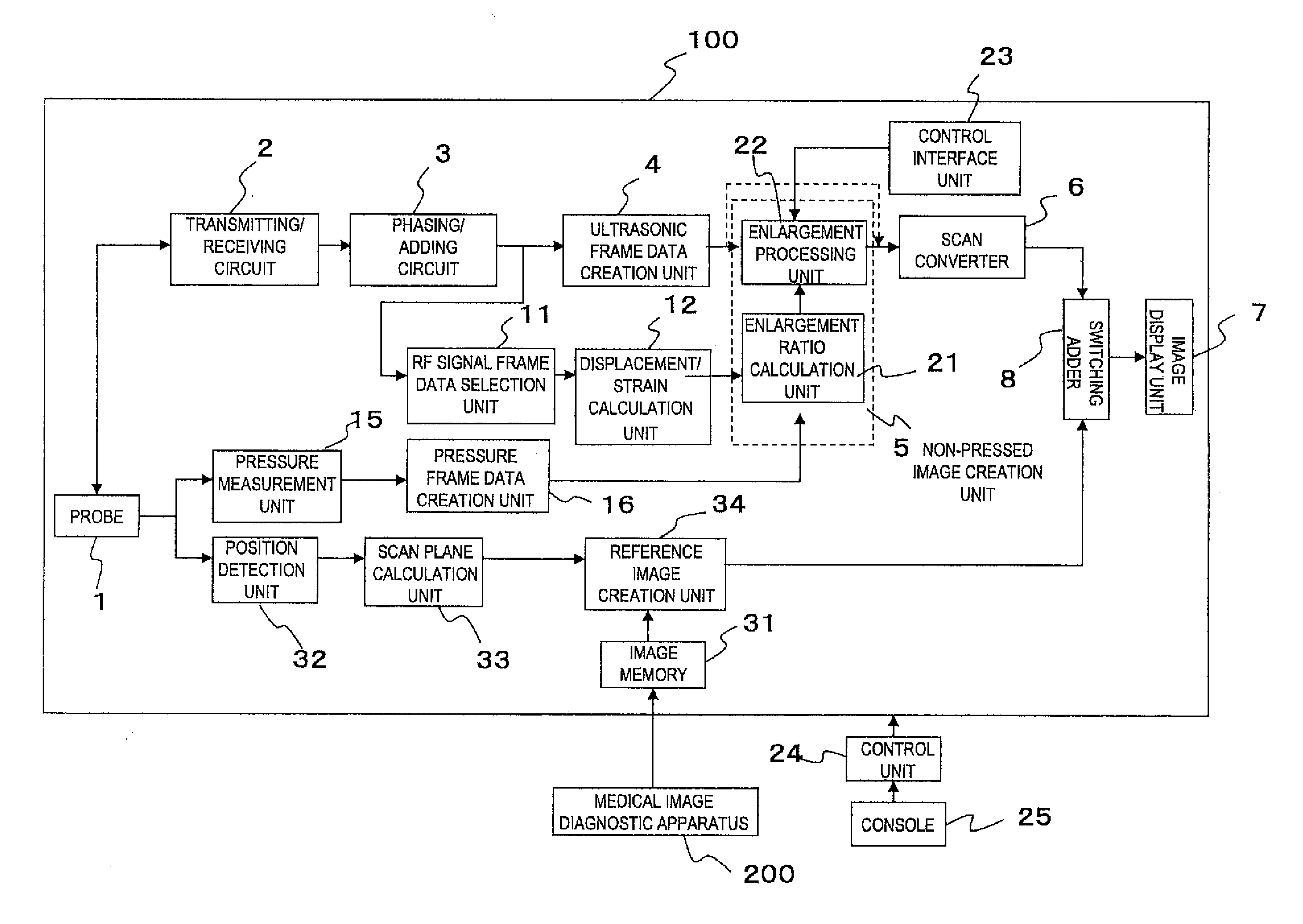
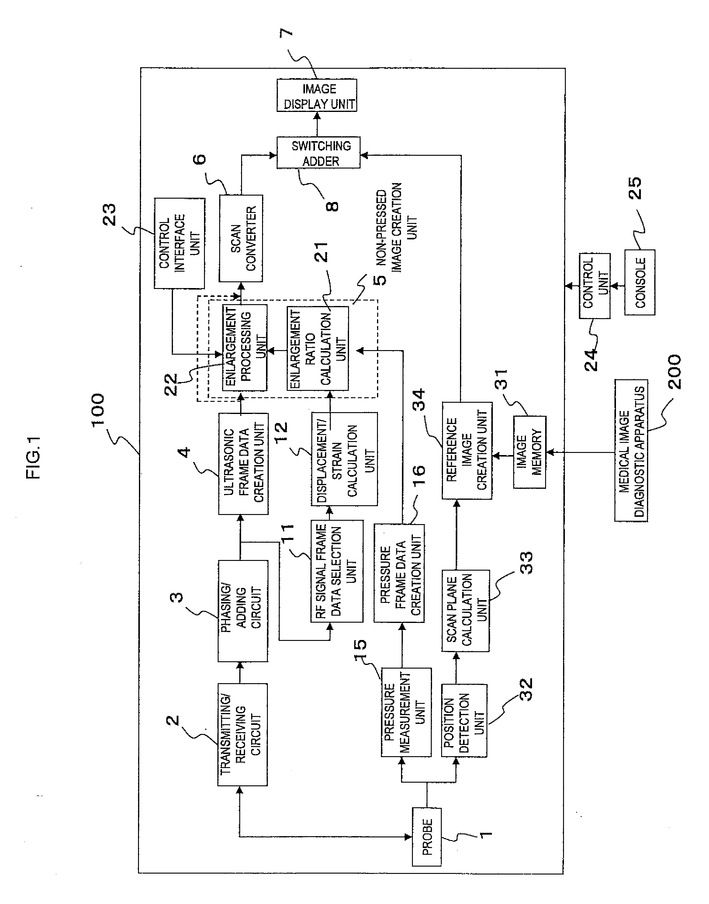
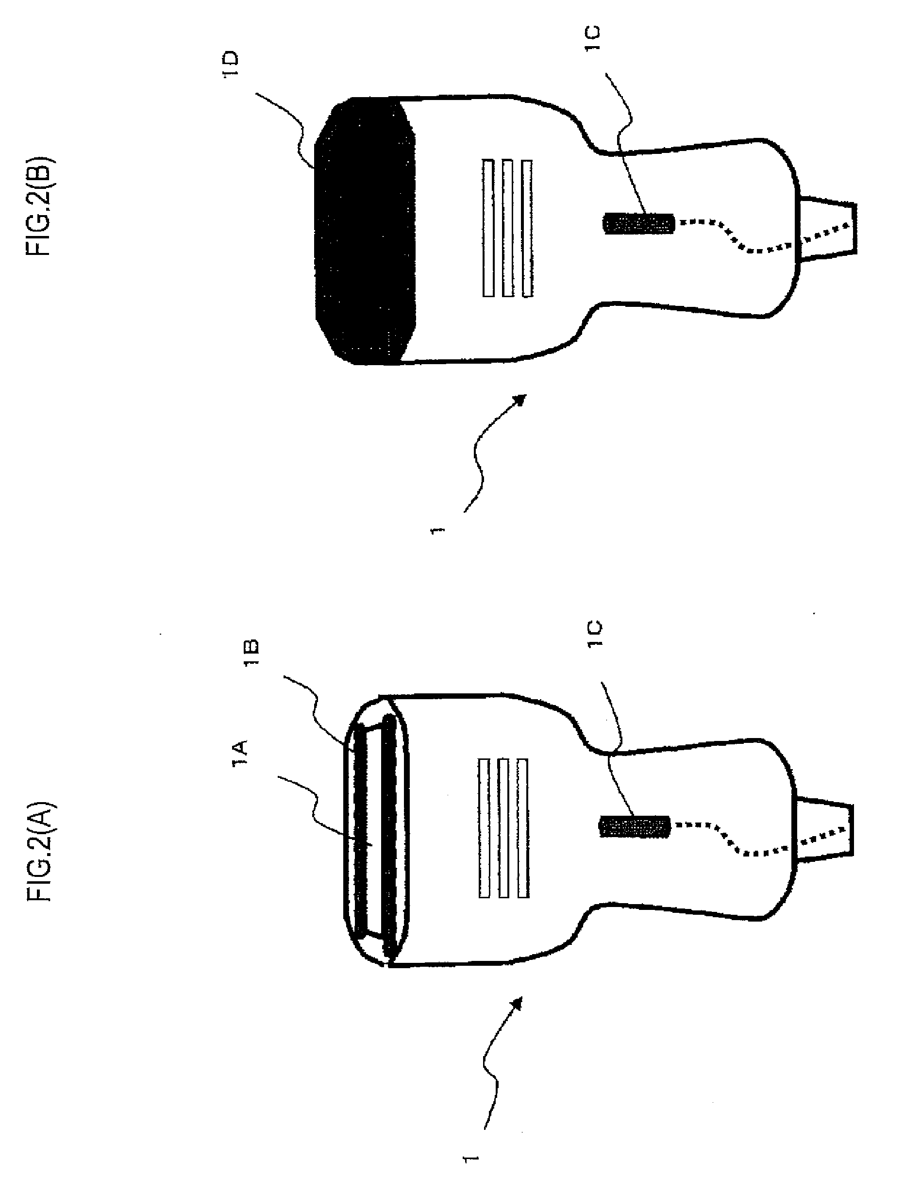
[0034]FIG. 1 is a schematic block diagram of an ultrasonic diagnostic apparatus according to an embodiment of the present invention. An ultrasonic diagnostic apparatus 100 shown in FIG. 1 includes an ultrasonic probe 1 which is pressed against an object (not shown) and transmits and receives an ultrasonic wave to and from the object. As shown in FIG. 2(A), the ultrasonic probe 1 is configured to include a plurality of ultrasonic transducers 1A arrayed on an ultrasonic transmission / reception surface. Upon driving of a transmitting / receiving circuit 2 (to be described later), each of the ultrasonic transducers 1A are sequentially scanned. The ultrasonic transducers 1A irradiate a scan plane in an object with an ultrasonic beam and receive a reflected echo wave generated from the scan plane in the object.

[0035]The transmitting / receiving circuit 2 generates and outputs an ultrasonic pulse for generating an ultrasonic wave to each of the ultrasonic transducers 1A of the ultrasonic probe ...

second embodiment

[0088]In the first embodiment, a corrected ultrasonic image which is obtained by correcting an ultrasonic image to have no strain and a reference image are comparatively observed. The present invention, however, is not limited to this. As in a second embodiment to be described below, the same advantages can be achieved even if a reference image and an ultrasonic image are comparatively observed after adding, to a reference image, a strain equivalent to one in an ultrasonic image.

[0089]FIG. 6 shows a block diagram of the second embodiment of an ultrasonic diagnostic apparatus according to the present invention. In FIG. 6, a block having the same functional configuration as in FIG. 1 is denoted by the same reference numeral, and a description thereof will be omitted. FIG. 6 is different from FIG. 1 in that ultrasonic frame data outputted from an ultrasonic frame data creation unit 4 is inputted to an image display unit 7 via a scan converter 6 and a switching adder 8. With this config...

third embodiment

[0100]Although a reference image is corrected on the basis of a microregion in the second embodiment, a reference image can be corrected line by line.

[0101]More specifically, at line coordinates X1 and X2, reduction ratios Ri,j at depth coordinates Y1 to Y9 are all 1.0, as shown in FIG. 8(A). Accordingly, it is determined that reduction processing need not be performed on pixels at the depth coordinates of the line coordinates X1 and X2. Pieces of luminance information at the depth coordinates Y1 to Y9 of the line coordinates X1 and X2 of reference image frame data RFD are transferred to corresponding coordinates of corrected reference image frame data OFD without change. That is, although enlargement processing is performed from the depth coordinate Y9 with a large depth to the depth coordinate Y1 with a small depth in the first embodiment, reduction processing is performed from the depth coordinate Y1 with the small depth to the depth coordinate Y9 with the large depth.

[0102]At a ...


PUM


Abstract

An ultrasonic diagnostic apparatus is characterized by including a displacement/strain calculation unit 12 which obtains a strain distribution of a body site on a scan plane when pressed by an ultrasonic probe 1 and a non-pressed image creation unit 5 which corrects an ultrasonic image on the basis of the strain distribution calculated by the displacement/strain calculation unit and generates a corrected ultrasonic image in a non-pressed state or a pressed image creation unit 40 which generates a corrected reference image obtained by adding, to the reference image, a strain equivalent to one in the ultrasonic image on the basis of the strain distribution obtained by the displacement/strain calculation unit 12, in order to accurately perform comparative observation of an ultrasonic image and a reference image captured by a medical diagnostic apparatus other than the ultrasonic diagnostic apparatus.

Description

TECHNICAL FIELD [0001]The present invention relates to an ultrasonic diagnostic apparatus and, more particularly, to a technique for pressing an ultrasonic probe against the body surface of an object and capturing an image.BACKGROUND [0002]An ultrasonic diagnostic apparatus which is an example of an image diagnostic apparatus is easy to handle and is capable of noninvasively observing an arbitrary section in real time. Ultrasonic diagnostic apparatuses are thus very often used for diagnosis.[0003]However, in ultrasonic diagnosis, an ultrasonic probe pressed against the body surface of an object and transmits and receives an ultrasonic wave in order to improve measurement sensitivity. Accordingly, a compressive force applied by the ultrasonic probe causes a body site in the object, such as an organ, to deform, and an ultrasonic image with strain is obtained.[0004]The process of measuring, e.g., the distance to, the area of, and the volume of each site of a living body from an ultraso...

Claims


Application Information

Patent Timeline
IPC IPC(8): A61B8/14
CPCA61B8/08A61B8/4254A61B8/469G01S7/5205A61B8/5276G01S7/52042A61B8/485
Inventor ARAI, OSAMUMATSUMURA, TAKESHI
Owner HITACHI MEDICAL CORP
Why Eureka
Try Eureka