Motor-driven steering lock apparatus

a technology of motor-driven steering and locking apparatus, which is applied in the direction of electrical locking circuit, anti-theft devices, lock applications, etc., can solve the problems of internal cpu failure to start, circuit structure to become complicated, internal cpu production of improper operation, etc., to achieve secure safety and reliability, simplify control circuit, and high safety

Inactive Publication Date: 2010-01-28
U SHIN LTD
View PDF6 Cites 5 Cited by
  • Summary
  • Abstract
  • Description
  • Claims
  • Application Information

AI Technical Summary

Benefits of technology

[0010]According to the present invention constructed by each of the means mentioned above, since the electric power is not fed to the driving means from the battery in the state in which the power feed from the host first control means to the drive control means is interrupted, the malfunction of the driving means can be securely prevented, and making it possible to secure a safety and a reliability.
[0011]Since the power feed to the drive control means is carried out by the host first control means, and the power feed to the driving means is carried out from the battery via the switching means, only one switching means is sufficient, and it is possible to simplify the control circuit.
[0012]Further, in accordance with the first means, even if the host first control means gets out of order, so as to be kept feeding to the drive control means, the driving means is not fed until the host second control means outputs the power supply-enabling signal. Further, even if the host second control means gets out of order, so as to lie outputting the power supply-enabling signal, the driving means is not fed until the host first control means outputs the feed signal. Further, even if the drive control means gets out of order, so as to lie outputting the drive signal to the driving means, the driving means is not fed until the feed signal of the host first control means and the power supply-enabling signal of the host second control means are output. Since the steering shaft is not locked during traveling of the vehicle unless a plurality of control means get out of order all together, it is possible to secure a high safety.
[0013]Further, in accordance with the second means, even if the host first control means gets out of order, so as to lie feeding to the drive control means, the driving means is not fed until the drive control means outputs the power supply-enabling signal. Further, even if the drive control means gets out of order, so as to lie outputting the drive signal to the driving means, the driving means is not fed until the feed signal of the host first control means is output. As mentioned above, since the steering shaft is not locked during traveling of the vehicle unless a plurality of control means get out of order all together, it is possible to secure a high safety.

Problems solved by technology

Further, there is a possibility that the internal CPU produces an improper operation during traveling of the vehicle.
However, it is necessary to provide a signal line for inputting a control signal in the switch means, causing a circuit structure to become complicated.
Further, as described in FIG. 11 of Japanese Unexamined Patent Publication No. 2002-308050, if the switch means is provided in the power supply line for feeding the power to the internal CPU and the electric motor, and the power supply to the both is interrupted during traveling, only the internal CPU cannot be started during traveling, making it impossible to execute the other controls (such as a confirmation of a lock and unlock state of a lock bolt during traveling of the vehicle) by the internal CPU.

Method used


Image

  • Motor-driven steering lock apparatus
  • Motor-driven steering lock apparatus
  • Motor-driven steering lock apparatus

Examples


first embodiment

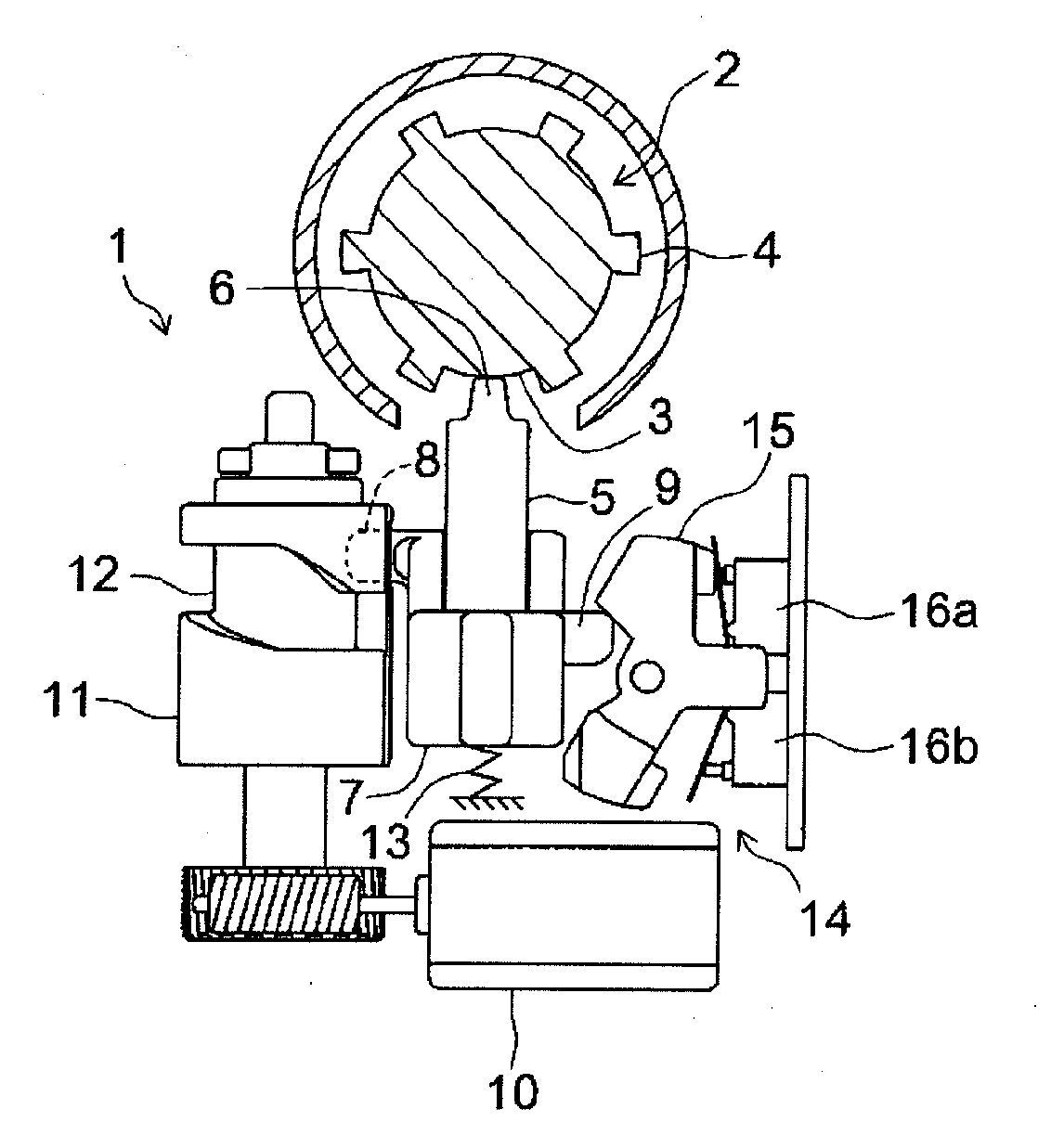
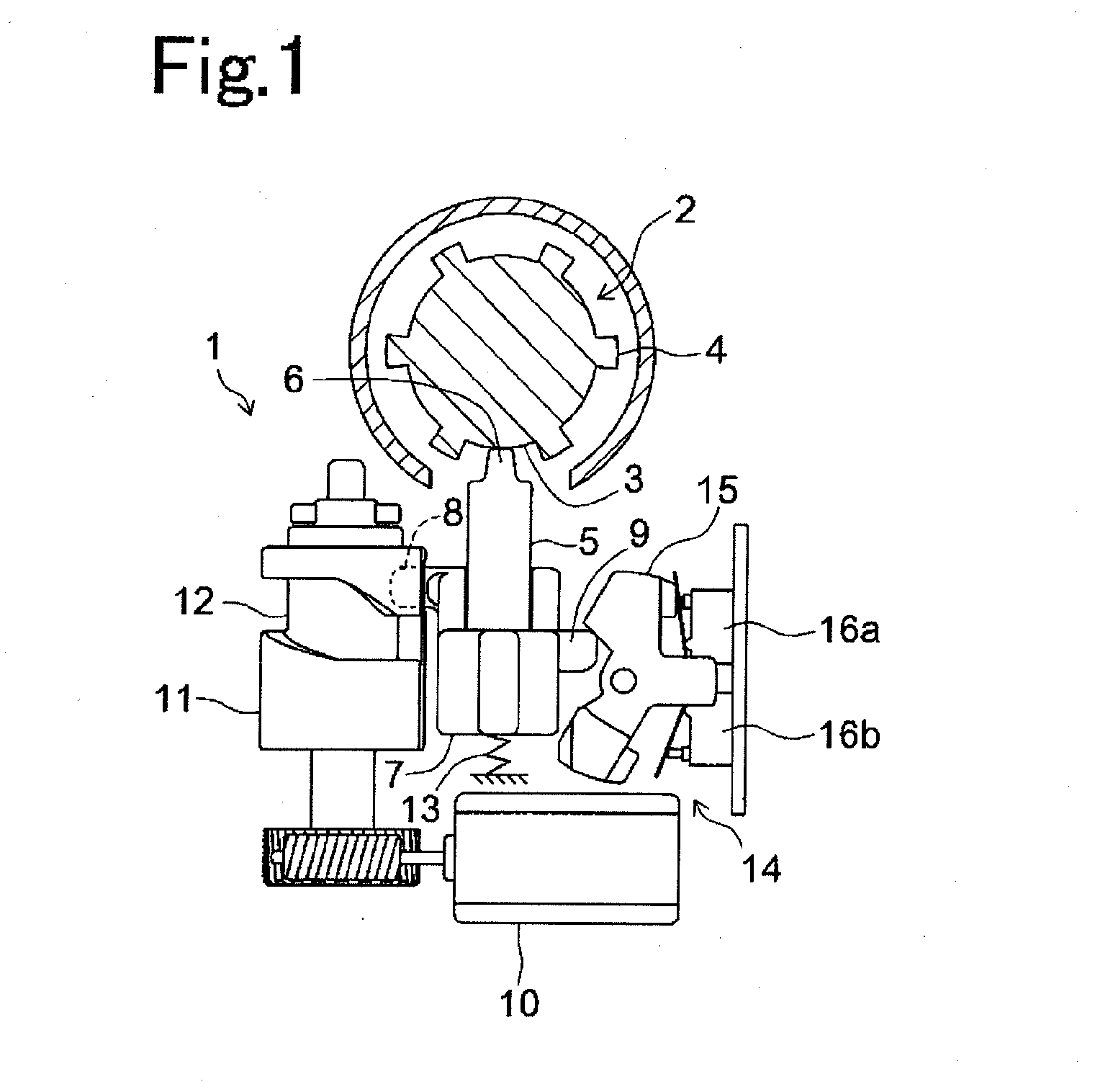
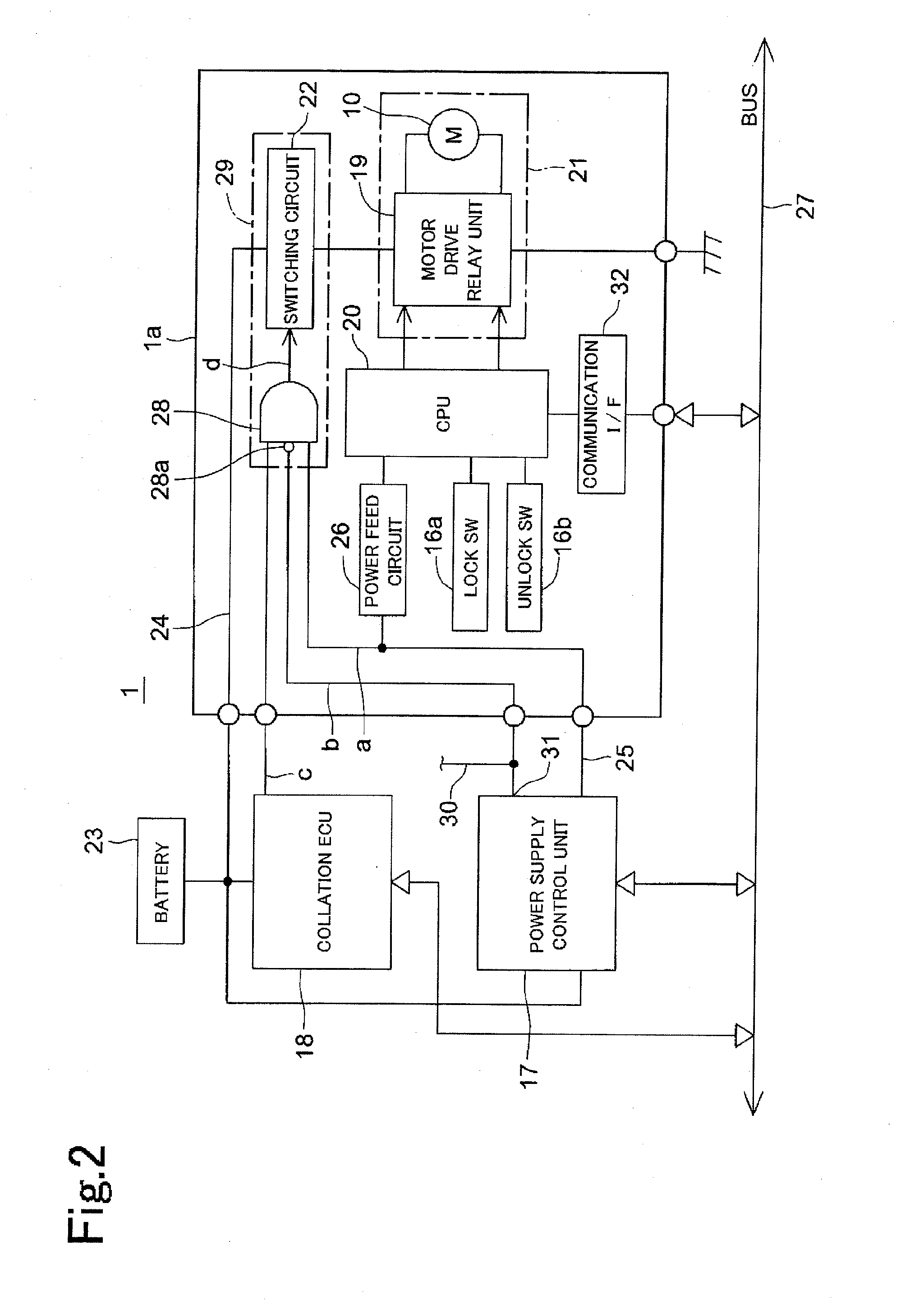
[0021]FIG. 2 shows a circuit diagram of the motor-driven steering lock apparatus 1 in accordance with a The motor-driven steering lock apparatus 1 has a motor-driven steering lock apparatus main body la, a power supply control unit 17 serving as a host first control means, and a collation ECU 18 serving as a host second control means.

[0022]The motor-driven steering lock apparatus main body la has an electric motor 10 driving the lock bolt 5, a motor drive relay circuit 19 feeding a power supply to the electric motor 10 so as to drive it, and a CPU 20 controlling the motor drive relay circuit 19 and serving as a drive control means in accordance with the present invention. The electric motor 10 and the motor drive relay circuit 19 construct a drive unit 21 serving as a driving means in accordance with the present invention.

[0023]An electric power is fed to the motor drive relay circuit 19 from a battery 23 via a switching circuit 22 through a power supply line 24. The motor drive re...

second embodiment

[0051]In the second embodiment, when the CPU 20 receives the unlock demand signal from the power supply control unit 17 at a time of starting the engine, the CPU 20 outputs the “motor power supply control signal on” to the AND circuit 28 via the signal line c. Further, the “ESL power supply on” and “IG power supply off” signals are output to the AND circuit from the power supply control unit 17, the AND circuit 28 outputs the on signal to the switching circuit 22. Accordingly, the switching circuit 22 turns on, and the power supply is fed to the electric motor 10 from the battery 23. After completing the unlock operation, the CPU 20 turns off the “motor power supply control signal”. Further, when the CPU 20 receives the lock demand signal from the power supply control unit 17 at a time of stopping the engine, the CPU 20 outputs the “motor power supply control signal on” to the AND circuit 22 via the signal line c, and turns off the “motor power supply control signal” after completin...


PUM


Abstract

The invention provides a motor-driven steering lock apparatus which can improve a reliability of locking and unlocking operations, with a simple circuit structure. A power supply line from a battery and a driving means are connected by a switching means only at a time when a feed signal from a host first control means to a drive control means (CPU), a power supply-enabling signal from the host first control means and a power supply-enabling signal from a host second control means are input to the switching means.

Description

FIELD OF THE INVENTION[0001]The present invention relates to a motor-driven steering lock apparatus.DESCRIPTION OF THE RELATED ART[0002]Conventionally, for example, a motor-driven steering lock apparatus of Japanese Unexamined Patent Publication No. 2002-308050 is structured such that a switch means is provided in a power supply line to an electric motor driving a lock bolt, and a power supply to the electric motor during traveling is interrupted by the switch means based on a signal from an external power supply control apparatus, for preventing the lock bolt from carelessly locking during traveling of a vehicle.[0003]However, the power supply line to an internal CPU controlling a driving direction of the electric motor is provided independently from the power supply line to the electric motor so that the internal CPU can carry out the other controls than the drive control of the electric motor even during traveling.[0004]Accordingly, the power supply is continuously fed to the int...

Claims


Application Information

Patent Timeline
Patent Type & Authority Applications(United States)
IPC IPC(8): E05B65/22B60R25/02B60R16/02B60R25/0215B60R25/021B60R25/04E05B81/56E05B83/00
CPCB60R25/02153Y10T70/5956
Inventor KUMANO, MASAKAZU
Owner U SHIN LTD
Why Eureka
Try Eureka