High Filling Flow Water Phantom
a water phantom and high filling flow technology, applied in the field of water phantoms, can solve the problems of cumbersome and time-consuming handling of these large scanning water phantoms, aggravate the drawback, and require additional time for conventional water phantoms, and achieve the effect of fast setup and fast measuremen
- Summary
- Abstract
- Description
- Claims
- Application Information
AI Technical Summary
Benefits of technology
Problems solved by technology
Method used
Image
Examples
second embodiment
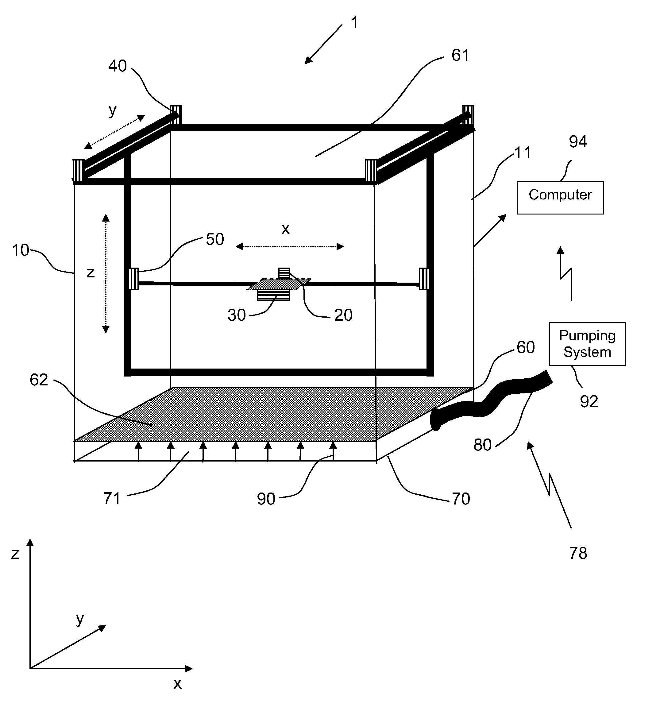
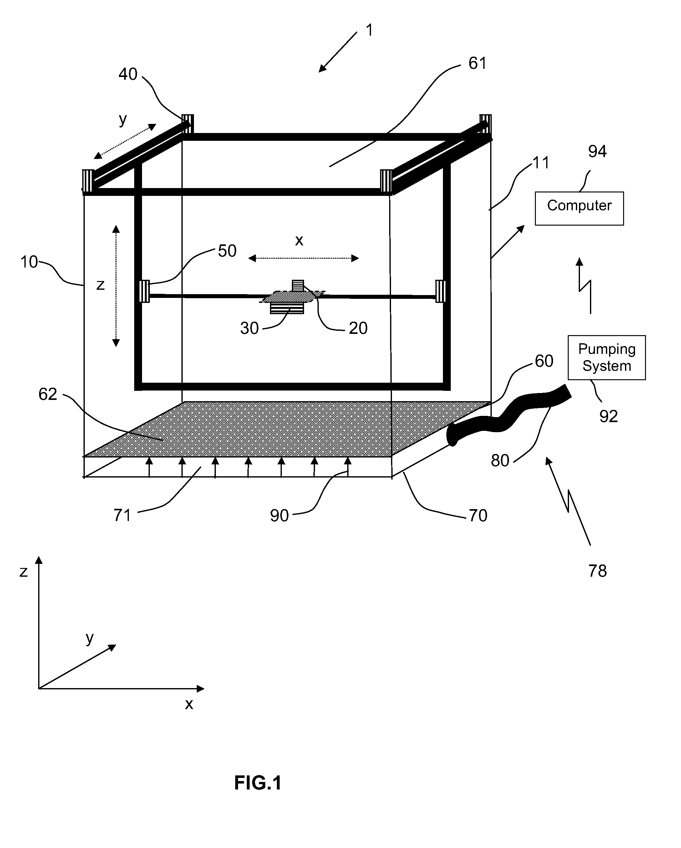
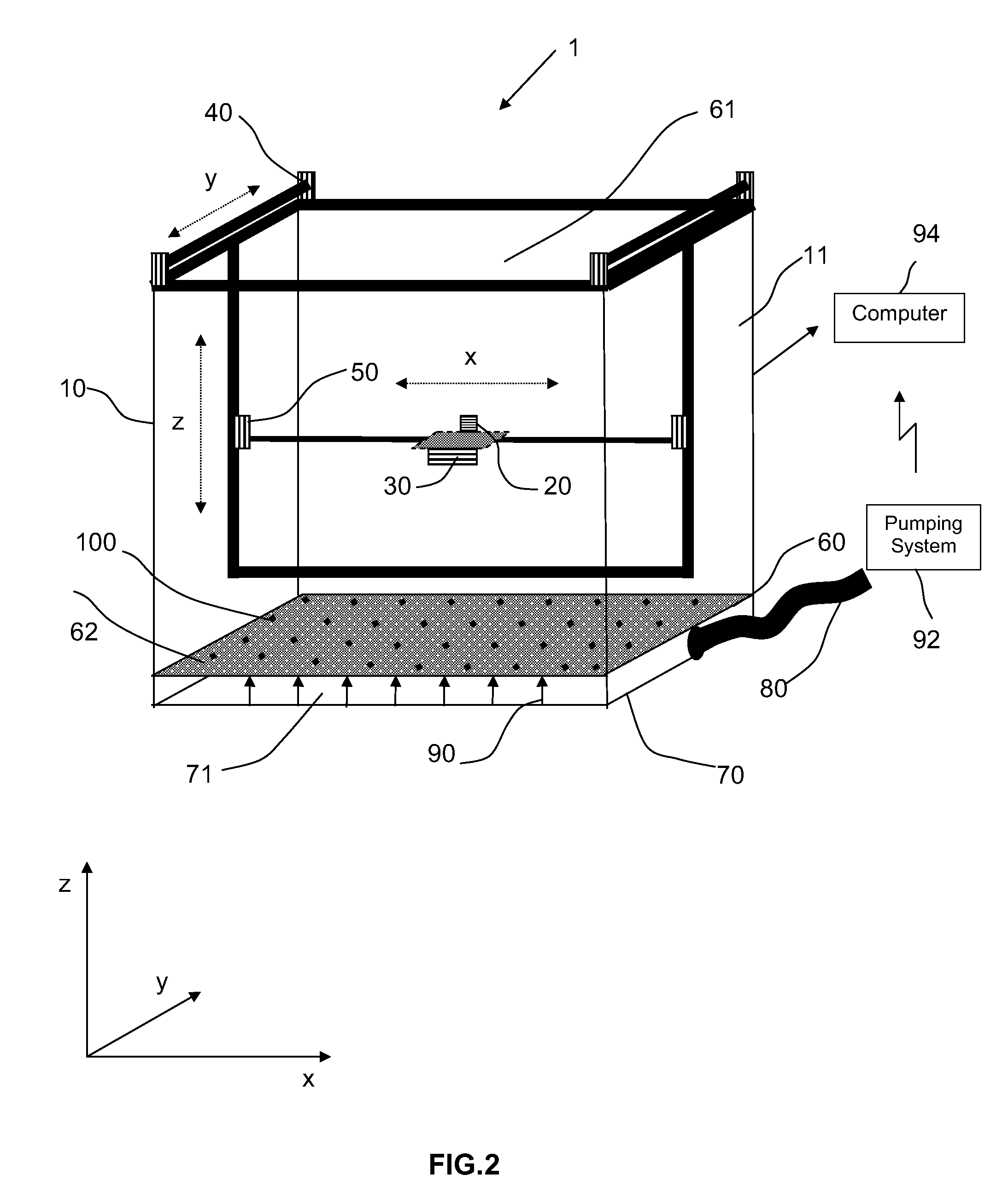
[0030]FIG. 2 is a perspective view of a water phantom according to a According to this embodiment the upper base 60 further comprises a detector comprised of a matrix of sensors 100 which are arranged on the surface of the upper base 60 in between the openings 62 in the upper base. In a basic configuration the matrix of sensors is made up of 169 diodes (13×13) evenly distributed over the upper base 60 (spacing between diodes approximately 3.5 cm). In a high-level configuration, the matrix may comprise a higher number of diodes along the central X-, Y-axes, and diagonals of the upper base 60 with a spacing of approximately 0.5 cm in order to measure central axis profiles with a high resolution. According to a variant of this embodiment, the matrix is made up of 1600 ionization chambers and has an active area of 40 cm×40 cm. Each ionization chamber has a diameter of 3.8 mm and a height of 2 mm and is spaced from the others with a pitch of 6.5 mm. This embodiment is particularly advan...
third embodiment
[0032]FIG. 4 is a perspective view of a water phantom according to a According to this embodiment, the lower base 70 has an irregular thickness so that the closed lower tank 71 presents a slanted shaped bottom surface having one of the four corners slightly deeper than the others. Since the connection line 80 connecting the pumping system to the closed lower tank 71 is opportunely located near this deeper corner, the presence of this slanted shaped bottom surface ensures that all water can be easily and quickly evacuated from the water tank 10 without having residual water within the water tank which could activate algae growth. It should be noticed that conventional water phantoms typically avoid this problem by manually raising one side of the water tank off the ground or by using expensive water filtration systems. It is evident that the water phantom according to this embodiment is less complex and less expensive with respect to conventional water phantoms.
[0033]FIG. 5 is a per...
fourth embodiment
[0034]FIG. 6 is a perspective view of a water phantom according to a variant of the The water phantom according to this variant is similar to the one represented in FIG. 3 wherein the acquisition detector 20 as well as the driving units 30, 40, 50 are removed and wherein measurements of TPR curves are provided by the plurality of detectors 100 arranged in between the openings 62 of the upper base 60. In this variant the closed lower tank 71 further has a slanted shaped bottom surface having one of the four corners slightly less deep with respect to the others.
[0035]The water phantom described herein presents following advantages:
[0036]One of the most significant drawbacks of the prior art is the enormous time amount usually required for the commissioning tests, especially when performing measurements in TPR configuration. By using the water phantom, the water phantom described herein can drastically reduce time by providing a water phantom which is configured to be filled with high...
PUM
 Abstract
Description
Claims
Application Information
 - R&D
- Intellectual Property
- Life Sciences
- Materials
- Tech Scout
- Unparalleled Data Quality
- Higher Quality Content
- 60% Fewer Hallucinations
Browse by: Latest US Patents, China's latest patents, Technical Efficacy Thesaurus, Application Domain, Technology Topic, Popular Technical Reports.
© 2025 PatSnap. All rights reserved.Legal|Privacy policy|Modern Slavery Act Transparency Statement|Sitemap|About US| Contact US: help@patsnap.com


