Excitation and Imaging Optics for Fluorescence Detection

a fluorescence detection and imaging optics technology, applied in the field of dna analysis, can solve the problems of limited size and lateral density of individual detection sites, difficult to meet the requirements of optical instruments for fluorescence measurement, and low light yield of this arrangemen

Active Publication Date: 2010-01-28
ROCHE MOLECULAR SYST INC
View PDF13 Cites 35 Cited by
  • Summary
  • Abstract
  • Description
  • Claims
  • Application Information

AI Technical Summary

Benefits of technology

[0037]means for heating and cooling a support with one or more wells e

Problems solved by technology

A major problem in fluorescence measuring devices is the enormous intensity of the excitation light in comparison to the fluorescence light which is emitted by the fluorescent marker and one therefore has to ensure that the excitation beam does not strike the detector in order to be able to exactly monitor the fluorescence signals.
However, when more than one fluorescent marker are present in the sample, it is necessary to monitor a lateral distribution of the positions on a solid support or the fluorescence of a microtitre plate (except when different dyes are present and detected in a single sample vessel) and the requirements of the optical instrument for the fluorescence measurement are more difficult to fulfill.
The scanning strategy has the obvious disadvantage that either the carrier has to be moved i

Method used


Image

  • Excitation and Imaging Optics for Fluorescence Detection
  • Excitation and Imaging Optics for Fluorescence Detection
  • Excitation and Imaging Optics for Fluorescence Detection

Examples


Embodiment Construction

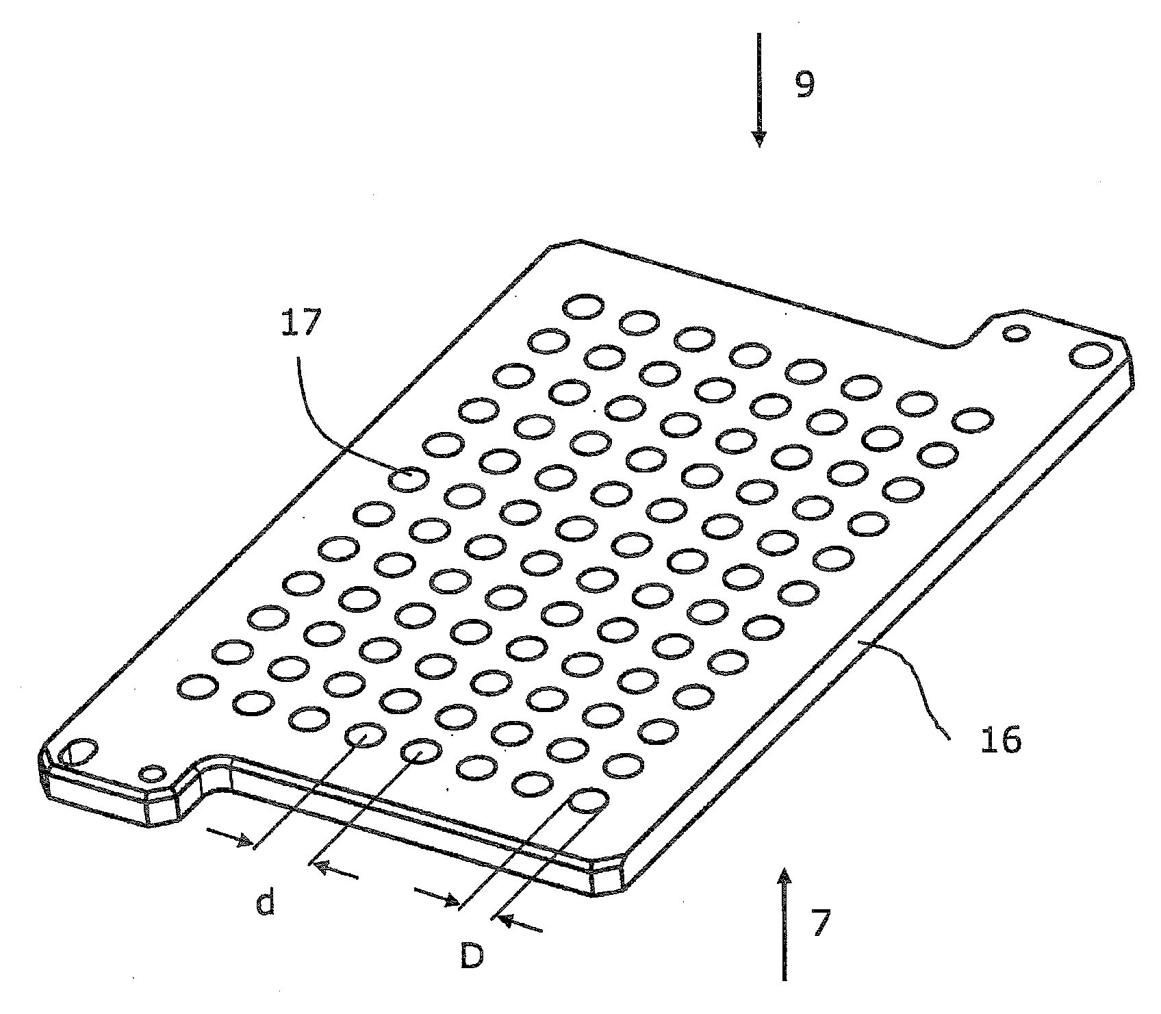
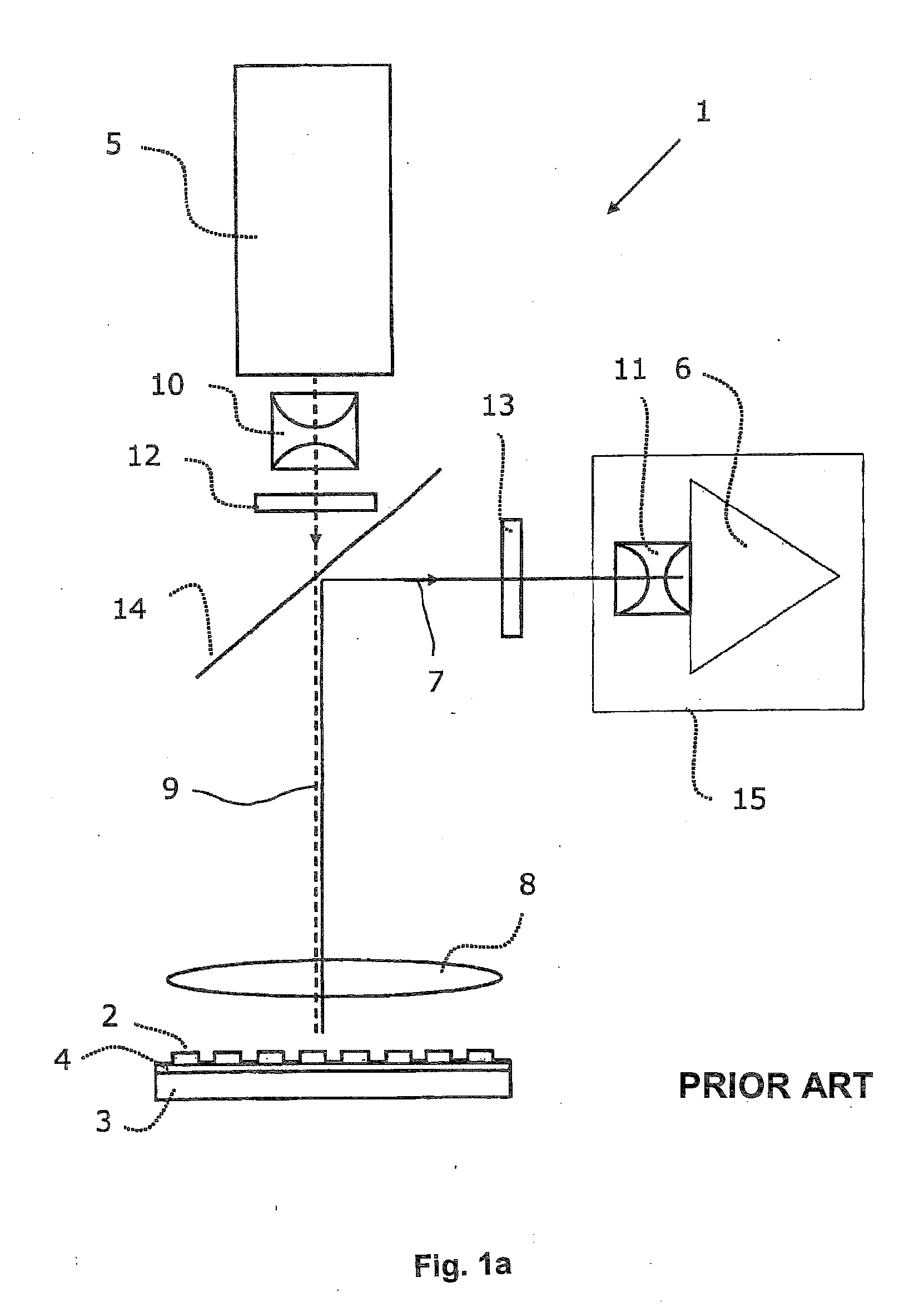
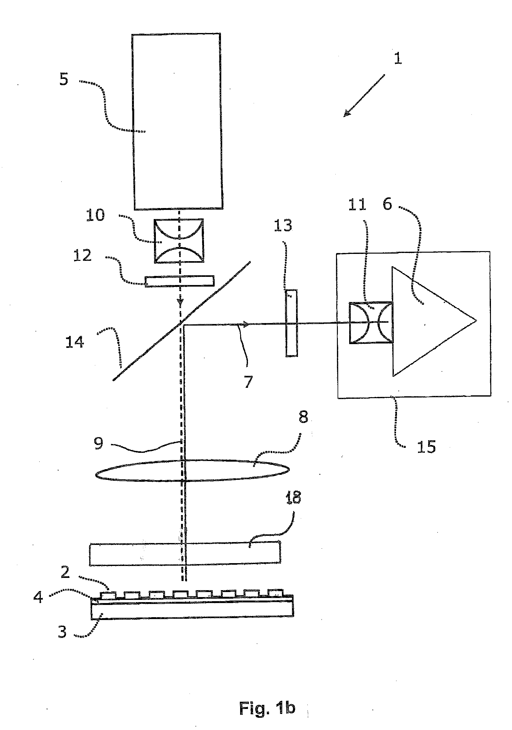
[0062]As mentioned hereinabove, the object of the present invention is to provide an improved device or an improved optical instrument for simultaneously monitoring fluorescence signals from a lateral distribution of a plurality of individual detection sites by optimizing the beam path with regard to a higher light yield. In one aspect of the present invention the problem to be solved relates to improvements in the monitoring of real-time multiplex PCR in a microtitre plate format.

[0063]Hence the invention is directed to an optical instrument for imaging fluorescence signals of an arrangement of a plurality of individual detection sites with a uniform excitation over the entire area of the arrangement, accurate imaging of the corresponding fluorescence signals and a high light yield.

[0064]This object is achieved according to the invention by an optical instrument having the features of patent claim 1. Various embodiments result from the dependent and independent patent claims and th...


PUM


Abstract

The invention concerns an optical instrument for imaging fluorescence signals from an arrangement of a plurality of individual detection sites, for example the wells of a microtitre plate. In order to improve the light yield of the fluorescence excitation with excitation light as well as the light yield of the detection of the fluorescence signals, an objective array is provided which is arranged in the beam path between the field lens and the detection sites and comprises a field lens array with field lens array elements and a pupil lens array with pupil lens array elements. In order to improve the channel separation and suppress interfering light the objective array can comprise a diaphragm array with in each case two diaphragm openings per detection site.

Description

CROSS-REFERENCE TO RELATED APPLICATION[0001]The present application claims the benefit of EP Appl. No. 08013392.9 filed Jul. 25, 2008, the content of which is hereby incorporated herein by reference in its entirety.FIELD OF THE INVENTION[0002]The present invention relates to the field of DNA analysis. In particular the present invention relates to a device for the parallel imaging of fluorescence intensities of a plurality of detection sites and in this connection in particular the excitation and imaging optics for the fluorescence detection of fluorescence signals.DESCRIPTION OF PRIOR ART[0003]In electrophoretic methods, proteins or DNA may be labelled with a fluorescent probe in order to visualize their electrophoretic bands in gels or columns. Furthermore, most of the previous applications of biochips are based on a fluorescence reading in which the specific binding of a fluorescently labelled target molecule to a probe molecule which is immobilized on a solid support is monitore...

Claims


Application Information

Patent Timeline
IPC IPC(8): G01T1/20
CPCG01N21/6452G02B3/0056G02B2207/113G02B21/16G02B27/0018G02B3/0062
Inventor FURLAN, ALANWIETZORREK, JOACHIM
Owner ROCHE MOLECULAR SYST INC
Why Eureka
Try Eureka