Electric powered vehicle, vehicle charge device and vehicle charge system

a technology of vehicle charge and charge device, which is applied in the direction of hybrid vehicles, electric devices, propulsion by batteries/cells, etc., can solve the problems of inability to activate the controller, inability to charge by external power supply, and inability to execute power conversion operation of power conversion devi

Active Publication Date: 2010-01-28
TOYOTA JIDOSHA KK
View PDF7 Cites 68 Cited by
  • Summary
  • Abstract
  • Description
  • Claims
  • Application Information

AI Technical Summary

Benefits of technology

[0026]According to the present invention, when an electric powered vehicle mounting a rechargeable power storage unit is charged by an external power supply, the electric power for oper

Problems solved by technology

Therefore, once the low voltage power storage unit enters the over-discharged state, that is, when the battery “goes flat” it becomes impossible to activate the controller even if external power is supplied to the elect

Method used


Image

  • Electric powered vehicle, vehicle charge device and vehicle charge system
  • Electric powered vehicle, vehicle charge device and vehicle charge system
  • Electric powered vehicle, vehicle charge device and vehicle charge system

Examples


embodiment 1

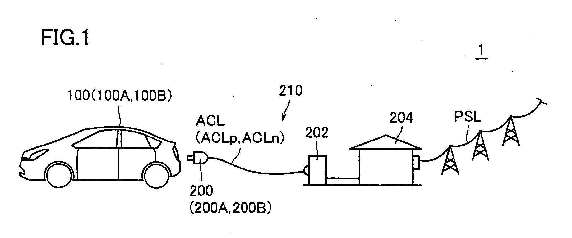
[0034]Referring to FIG. 1, a vehicle charge system 1 in accordance with Embodiment 1 of the present invention includes an electric powered vehicle 100 and a vehicle charge device 210.

[0035]Electric powered vehicle 100 generally refers to a vehicle having an electric motor as a source of driving force and a power storage unit for supplying electric power to the electric motor mounted thereon, and it includes at least an electric vehicle, a hybrid vehicle and a fuel cell vehicle. In the present embodiment, a hybrid vehicle having an electric motor and an engine mounted thereon and running with driving forces from the motor and the engine adjusted to an optimal ratio will be described as electric. powered vehicle (hereinafter simply referred to as a “vehicle”) 100.

[0036]Vehicle charge device 210 is for charging a power storage unit mounted on vehicle 100 by a commercial power supply as an example of external power supply, and it includes a connector unit 200 and a charging station 202....

embodiment 2

[0083]In Embodiment 1 above, a configuration has been described in which low voltage power generating unit 4 for passively generating low voltage power is mounted on the side of vehicle 100. In Embodiment 2, a configuration will be described in which the low voltage power generating unit 4 is provided on the side of vehicle charge device.

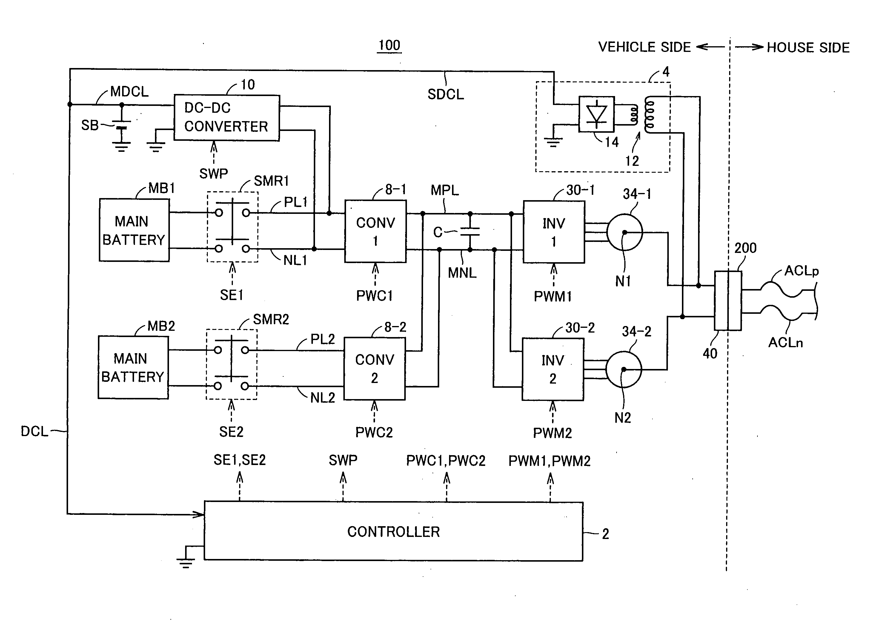
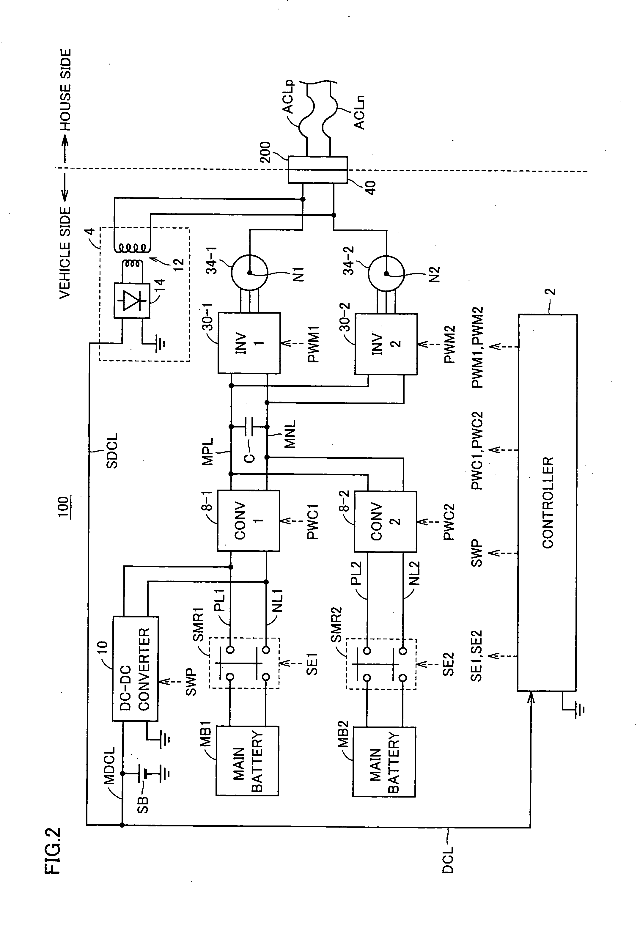
[0084]Referring to FIG. 5, a vehicle 100A constituting the vehicle charge system in accordance with Embodiment 2 of the present invention corresponds to vehicle 100 shown in FIG. 2, not including low voltage power generating unit 4 and having, in place of connector receiving portion 40, a connector receiving portion 40A that can receive the low voltage power generated by the vehicle charge device, in addition to the commercial power supply. Further, a connector unit 200A constituting the vehicle charge device in accordance with Embodiment 2 corresponds to connector unit 200 shown in FIG. 2, having low voltage power generating unit 4 provided therein...

embodiment 3

[0089]In Embodiment 1 above, a configuration has been described in which low voltage power generating unit 4 mounted on the side of vehicle 100 passively generates low voltage power. In Embodiment 3, a configuration will be described in which the low voltage power is generated by lowering the output voltage of the main battery.

[0090]Referring to FIG. 6, vehicle 100B in accordance with Embodiment 3 of the present invention corresponds to vehicle 100 shown in FIG. 2, additionally. including a voltage lowering unit 5, system relays SMR3 and SMR4, and a connector receiving unit 40B with an identification tag 42. Further, connector unit 200B in accordance with Embodiment 3 of the present invention corresponds to connector unit 200 in accordance with Embodiment 1 of the present invention, additionally including a detecting unit 44 for detecting the identification tag 42 and a command generating unit 46 for generating a system enable signal SE3 for driving system relays SRM3 and SRM4 of ve...


PUM


Abstract

A vehicle has a low voltage power generating unit mounted thereon, which passively generates low voltage power when the vehicle is electrically connected to commercial power supply through coupling of a connector unit. A winding transformer transforms the commercial power supply input to the primary side with a prescribed ratio of transformation, and the transformation is performed without requiring any control signal from the outside. The AC power with voltage lowered, output from the secondary side of winding transformer, is rectified by a diode unit, and a low voltage power is generated. The low voltage power generated by the diode unit is supplied through a supplementary low voltage DC line to a sub battery and to a controllers.

Description

TECHNICAL FIELD[0001]The present invention relates to an electric powered vehicle having a rechargeable power storage unit that can be charged by an external power supply, a vehicle charge device for-charging the electric powered vehicle, and a vehicle charge system including these. More specifically, the present invention relates to a scheme for ensuring electric power necessary for control operation when the power storage unit is charged.BACKGROUND ART[0002]Recently, in consideration of environmental issues, an electric powered vehicle such as an electric vehicle, a hybrid vehicle or a fuel cell vehicle has attracting attention. Such an electric powered vehicle has a rechargeable power storage unit mounted thereon, to supply electric power to an electric motor, and to convert kinetic energy to electric energy for storage at the time of regenerative braking.[0003]Conventionally, a vehicle charge system for charging the power storage unit mounted on such an electric powered vehicle ...

Claims


Application Information

Patent Timeline
IPC IPC(8): H02J7/00B60L1/00H02J7/02
CPCB60L11/123Y02T90/14B60L11/1812B60L11/1814B60L11/1816B60L11/1824B60L15/007B60L2210/20B60L2220/14B60L2220/54Y02T10/6217Y02T10/641Y02T10/7005Y02T10/7077Y02T10/725Y02T90/121Y02T90/127B60L11/14B60L50/16B60L50/61B60L53/18B60L53/22B60L53/24Y02T10/62Y02T10/64Y02T10/70Y02T10/7072Y02T10/72Y02T90/12
Inventor ICHIKAWA, SHINJI
Owner TOYOTA JIDOSHA KK
Why Eureka
Try Eureka