Lightweight Electromagnetic Interference Filter

Active Publication Date: 2010-01-28
HAMILTON SUNDSTRAND CORP
View PDF3 Cites 23 Cited by
  • Summary
  • Abstract
  • Description
  • Claims
  • Application Information

AI Technical Summary

Benefits of technology

[0005]The invention is a low pass filter that replaces inductors with capacitors in the damping portion of the circuit. The resulting low pass filter significant

Problems solved by technology

Electromagnetic interference, or “noise,” is a common problem in electrical circuit design.
Noise may originate from natural sources, such as background

Method used


Image

  • Lightweight Electromagnetic Interference Filter
  • Lightweight Electromagnetic Interference Filter
  • Lightweight Electromagnetic Interference Filter

Examples


Example

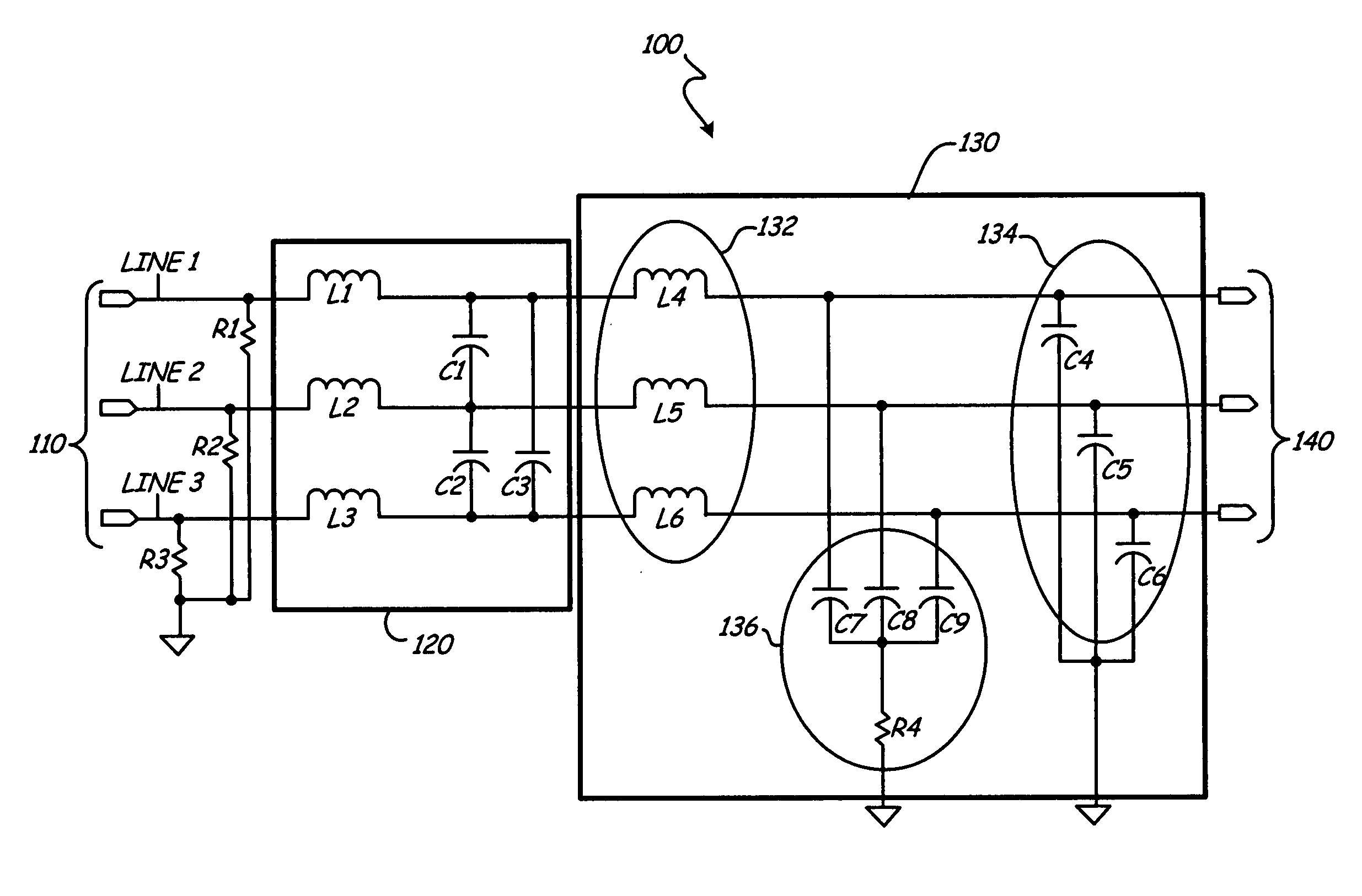
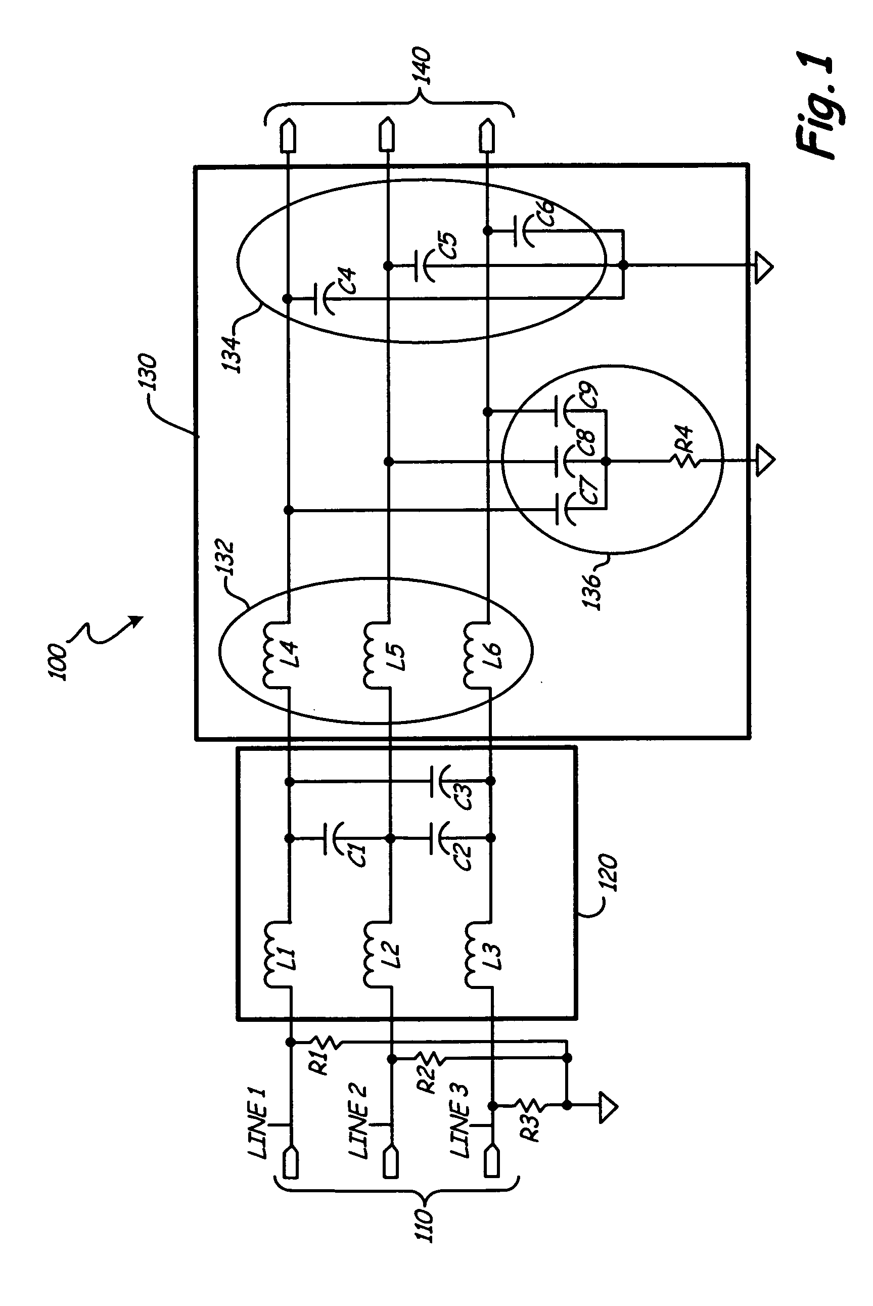
[0008]FIG. 1 is a schematic diagram that shows low pass filter circuit 100 according to an embodiment of the invention. Low pass filter circuit 100 includes three inputs 110, pull-down resistors R1, R2 and R3, differential mode filter 120, common mode filter 130 and three outputs 140. There are three signal lines (or “rails”) in low pass filter circuit 100, identified in FIG. 1 as line 1, line 2 and line 3. Low pass filter circuit 100 filters out electromagnetic noise in electrical circuits, particularly noise affecting electrical circuits in aircraft.

[0009]Electromagnetic noise includes two components: differential mode noise and common mode noise. Differential mode noise results from current flowing from a positive voltage terminal, through a load and returning through a negative voltage terminal. Common mode noise results from current flowing from a lead, through a load and returning through the ground terminal. Noise filtering circuits must eliminate both common mode noise and d...


PUM


Abstract

A low pass filter includes a differential mode filter and a common mode filter. The common mode portion of the filter includes at least one inductor and one capacitor, as well as a damping circuit with at least one capacitor. The low pass filter has a reduced weight, which is useful in circumstances in which weight is a significant factor, such as in aircraft.

Description

BACKGROUND[0001]This invention relates generally to circuits for filtering electromagnetic noise. More specifically, the invention relates to a low pass filter with reduced weight for use in aircraft.[0002]Electromagnetic interference, or “noise,” is a common problem in electrical circuit design. Noise may originate from natural sources, such as background radiation or lightning strikes, but the more common and more problematic noise is electromagnetic noise generated by components in electrical systems. Modern aircraft include numerous electrical systems, so filtering of electromagnetic noise is a significant concern.[0003]Filtering circuits are used to reduce the effect of electromagnetic noise in the electrical systems of aircraft. Electromagnetic noise signals are high frequency signals, so filtering circuits are usually designed as low pass filters, which allow the desirable low frequency signals to pass through a circuit, while filtering out the undesirable high frequency elec...

Claims


Application Information

Patent Timeline
IPC IPC(8): H03H7/06
CPCH02M1/126H02M2001/123H03H7/427H03H7/1725H03H7/06H02M1/123
Inventor FENG, FRANK Z.SCHMIU, DWIGHT D.BAKER, DONAL E.HUSS, JOHNWHITE, CURTIS B.SHAFII, JAMALSTUNKEL, MARK F.
Owner HAMILTON SUNDSTRAND CORP
Why Eureka
Try Eureka