Supercharge Your Innovation With Domain-Expert AI Agents!

Communication System, Optical Line Terminal, and Congestion Control Method

Inactive Publication Date: 2010-01-28
HITACHI LTD
View PDF5 Cites 28 Cited by
  • Summary
  • Abstract
  • Description
  • Claims
  • Application Information

AI Technical Summary

Benefits of technology

[0015]Accordingly, an object of the present invention is to prevent degraded switching responses caused by congestion in the OLT by IGMP requests sent by users for video channel switching (MC group changes) even if FTTH users increase in the future and users for which the OLT provides services increase.
[0016]Another object of the present invention is to prevent degraded channel switching responses caused by congestion in the OLT by a large number IGMP requests sent by many users, made possible by the future technical progress.
[0018]To solve the above-described problem, an MC group processing function section provided for an L2SW in an OLT manages the number of users who are watching each channel (for example, the number of ONTs participating in each MC group) by a table in the present invention. When the number of users who participates in an identical MC group exceeds a threshold (this threshold can be changed as desired by an OLT administrator or maintenance person) defined in advance in a table in the L2SW, the OLT makes a delay buffer in the OLT generate, in addition to the MC group to which distribution has been performed so far (hereinafter an MC group to which a delay is not given by the delay buffer in the OLT is called a usual MC group), an MC group (hereinafter called a delayed MC group) to which the same data, for example, the same content, as that distributed to the usual MC group is distributed but the distribution time is delayed by about several seconds from that for the usual MC group, after the L2SW changes the multicast IP address of the usual MC group. Then, the L2SW requests each ONT to make an IGMP processor in the ONT convert, when an STB sends a join request for joining the usual MC group by using IGMP, the join request for joining the usual MC group to a join request for joining the delayed MC group and to send the join request to the OLT. With this processing, when a user, for example, an STB, sends a new join request for joining the usual MC group for which the threshold has been exceeded, the user is accommodated into the delayed MC group. When the number of users participating in the delayed MC group reaches the threshold, another delayed MC group having a further increased delay is generated, and a new user who wants to join the usual MC group is accommodated into this another delayed MC group. In this manner, when the threshold specified in advance in the OLT is exceeded, a delayed MC group to which the same video data as that distributed to the usual MC group is distributed but the distribution time is delayed by several seconds from that for the usual MC group is generated, and a new user is accommodated into the delayed MC group. Repeating this operation prevents the number of users participating in one MC group from reaching or exceeding the threshold specified in the L2SW of the OLT and prevents participating users from centering on a specific MC group.
[0019]When the number of users participating in one MC group is limited by using the above-described method, the video watching timing, such as the start or end of a broadcasting time, of each user controlled by the OLT for an identical video data is different between the usual MC group and each delayed MC group even at the end of a program having a very high audience rating or the start of a commercial. Therefore, the end time of a video program or the start time of a commercial is dispersed among MC groups. The present invention reduces the probability that STBs disposed at the houses of many users send IGMP requests for channel switching (for changing the MC group) at the same time to the OLT and prevents a large number of IGMP requests from reaching the OLT at the same time.
[0053]Even if FTTH users increase in the future and users for which the OLT provides services increase, the present invention can prevent degraded switching responses caused by congestion in the OLT by IGMP requests sent by users for video channel switching (MC group changes).
[0055]The present invention can prevent degraded channel switching responses caused by congestion in the OLT by a large number IGMP requests sent by many users, made possible by the future technical progress.

Problems solved by technology

In such a situation, when a large number of users, such as STBs, switch the channels (meaning that change the multicast groups) at the same time under one OLT in an IP video multicast distribution, which is one of main services of triple play, a problem may arise.
In such a case, the MC group processing function section cannot handle the IGMP requests for MC group changes sent from the STBs in some cases, leading to deterioration and delays in channel switching responses and then adversely affecting communication quality.

Method used


Image

  • Communication System, Optical Line Terminal, and Congestion Control Method
  • Communication System, Optical Line Terminal, and Congestion Control Method
  • Communication System, Optical Line Terminal, and Congestion Control Method

Examples


first embodiment

1. First Embodiment

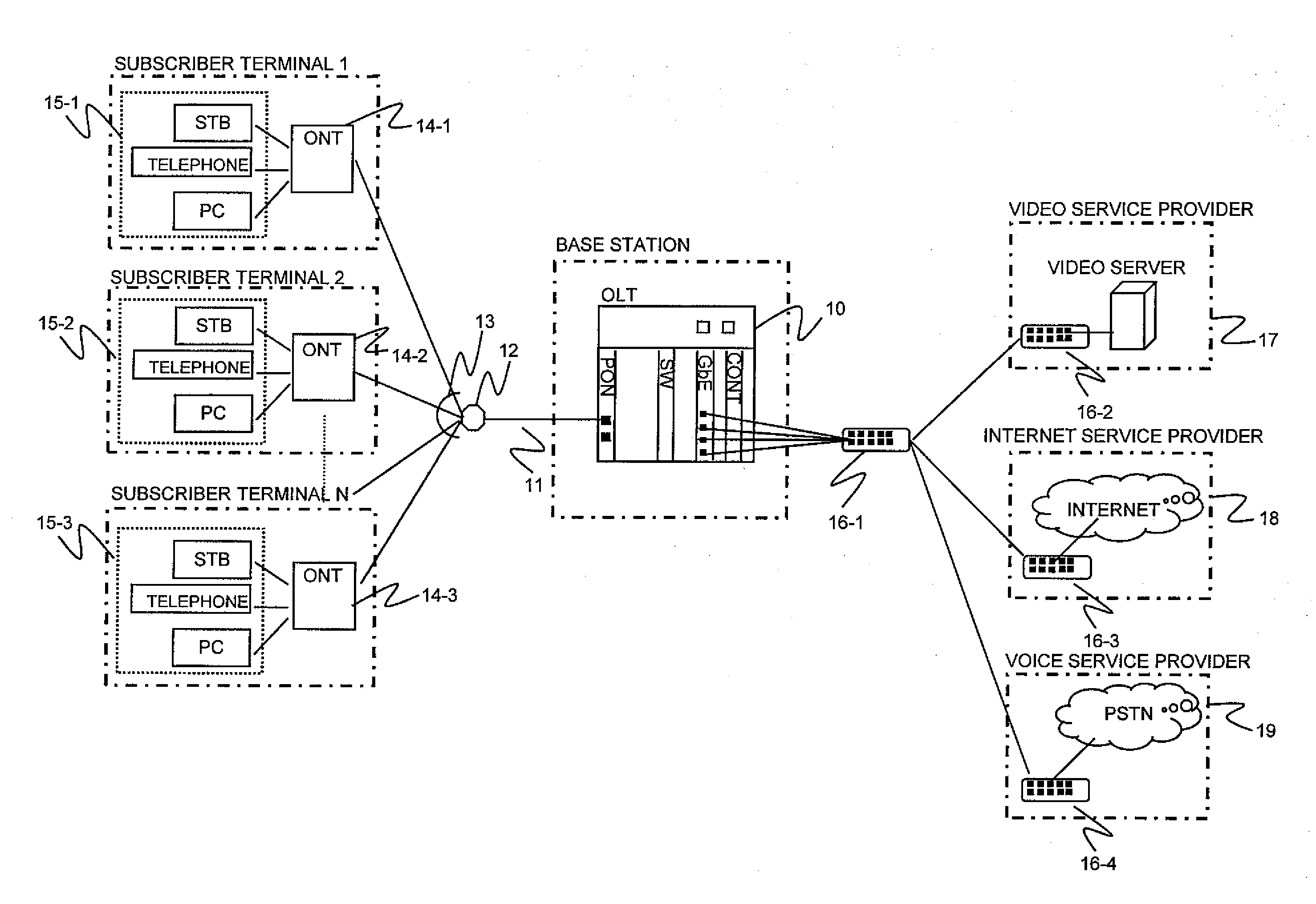
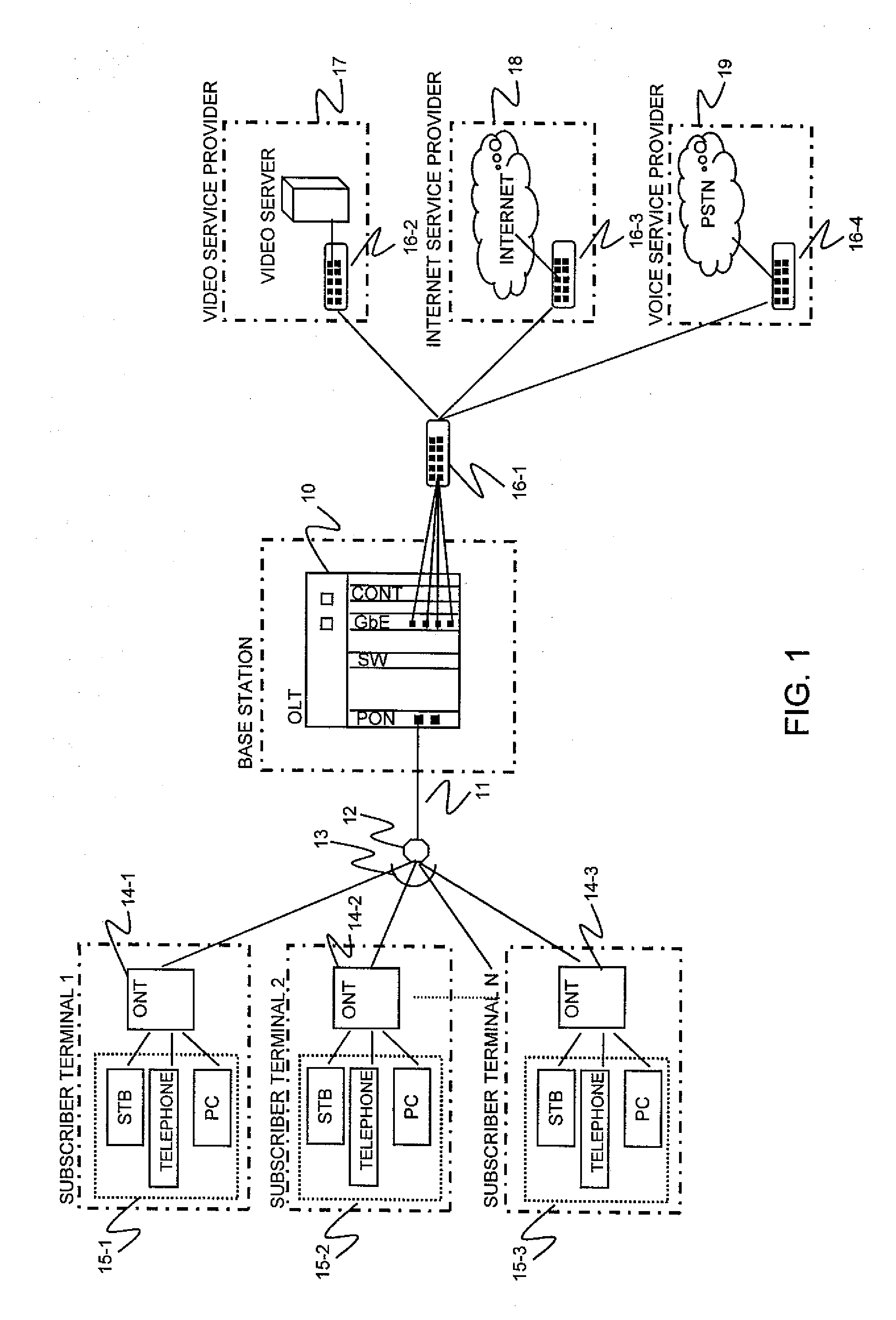
[0075]As shown in FIG. 1, the present invention is applied to the network where the OLT 10 is connected to the optical splitter 12 through the core optical fiber 11 and the optical splitter 12 is connected to the ONTs 14-1 to 14-3 through the plurality of local optical fibers 13. Hardware structure

[0076]FIG. 3 is a block diagram of a passive optical network (PON) system to which the present invention is applied.

[0077]The PON system includes, for example, an OLT 300, a plurality of STBs 301-1 and 301-2, a plurality of ONTs 302-1 and 302-2, a plurality of optical splitters 303-1 to 303-2, a router 310 capable of multiple multicast, and video servers 311-1 and 311-2 for distributing video data to users. The OLT 300 includes, for example, a plurality of PON cards 304-1 and 304-2, a delay buffer 305 for giving a delay to an MC group, a delayed MC group management table 306 provided inside or outside an L2SW, a plurality of L2SW cards 307-1 and 307-2 serving as IGMP pro...

second embodiment

2. Second Embodiment

Hardware Structure

[0131]FIG. 14 shows the structure of a PON system according to a second embodiment of the present invention.

[0132]The PON system of the second embodiment includes an MC group re-arrangement table 331 in addition to the structure of the PON system of the first embodiment.

Table Structure

[0133]FIG. 13 shows the format of the MC group re-arrangement table 331.

[0134]The MC group re-arrangement table 331 is generated by using the delayed MC group management table (see FIG. 6). MC groups for which a join is possible in the delayed MC group management table (see FIG. 6) are arranged in an ascending order of delay, with re-arrangement numbers 1300 attached. The other elements are the same as those in the delayed MC group management table (see FIG. 6).

Operation

[0135]FIG. 12 is a flowchart of processing in the second embodiment.

[0136]The flowchart of FIG. 12 in the second embodiment is the same as the flowchart of FIG. 10 in the first embodiment except tha...


PUM


Abstract

Congestion caused by a large number of IGMP requests sent from set top boxes at channel switching is prevented in an optical line terminal (OLT). An IGMP processing section in the OLT has a delayed data generation threshold and a delayed data transmission threshold. When the number of ONTS participating in a multicast group is increased, the OLT generates a delayed multicast group for video data. The delayed multicast group having a few second delay accommodates a new user. With this, the end time of a highly popular program and a commercial start time are shifted among users to prevent, in the OLT, congestion caused by IGMP requests sent for channel switching at an identical time point.

Description

CLAIM OF PRIORITY[0001]The present application claims priority from Japanese patent application JP 2008-192740 filed on Jul. 25, 2008, the content of which is hereby incorporated by reference into this application.BACKGROUND OF THE INVENTION[0002]1. Field of the Invention[0003]The present invention relates to communication systems, optical line terminals (OLTs), and congestion control methods, and more particularly, to a communication system, an optical line terminal, and a congestion control method for preventing Internet group management protocol (IGMP) requests generated when video service viewing users switch the channels, from congesting in the optical line terminal in a passive optical network (PON).[0004]2. Description of the Related Art[0005]To transmit and receive large-size data and image signals through communication networks, the networks have been improved to have a higher rate and a wider band. PONs, which are defined by “Gigabit-capable passive optical network (GPON)”...

Claims


Application Information

Patent Timeline
IPC IPC(8): H04L12/56H04L12/44H04L12/70H04N7/22H04N21/61
CPCH04L12/1877H04L12/1881H04L49/90H04L65/80H04Q11/0067H04Q2011/0079H04L65/4076H04N21/4383H04L65/611
Inventor KOMIYA, KENTAKURATA, RYOSUKEKAZAWA, TOHRU
Owner HITACHI LTD
Features
  • R&D
  • Intellectual Property
  • Life Sciences
  • Materials
  • Tech Scout
  • Unparalleled Data Quality
  • Higher Quality Content
  • 60% Fewer Hallucinations
Learn More