Optical communications system without using a special-purpose evaluation signal

a communication system and special-purpose technology, applied in the field of optical communication systems, can solve the problems of consuming an excess band for measurement, affecting the overall validity of patent document 2, and fixed band degradation

Inactive Publication Date: 2010-01-28
NEC CORP
View PDF13 Cites 14 Cited by
  • Summary
  • Abstract
  • Description
  • Claims
  • Application Information

AI Technical Summary

Benefits of technology

[0014]An exemplary object of the invention is to provide a communications method that it is unnecessary to use a special-purpose evaluation signal.

Problems solved by technology

However, in the above-mentioned general PON system illustrated in FIG. 1, the overhead of parity of the error correction is constantly added independent of a line state and it results in fixedly degradation of a band.
However, Patent Document 2 comprehensively does not keep in mind various environmental conditions in an optical transmission path such as the number of branches of the optical transmission path, the luminous intensity of transmission light, strength of a received signal, the presence or absence of a relay station, performance of the relay station, and so on.
Accordingly, it results in consuming an excess band for the measurement.

Method used


Image

  • Optical communications system without using a special-purpose evaluation signal
  • Optical communications system without using a special-purpose evaluation signal
  • Optical communications system without using a special-purpose evaluation signal

Examples


Embodiment Construction

:

[0026]A gigabit Ethernet-passive optical network (G-EPON) system is a system which is constructed by equipping Ethernet (registered trademark) into a passive optical network (PON) system. The description will be made as regards exemplary embodiments of the present invention which are applicable to the G-EPON system.

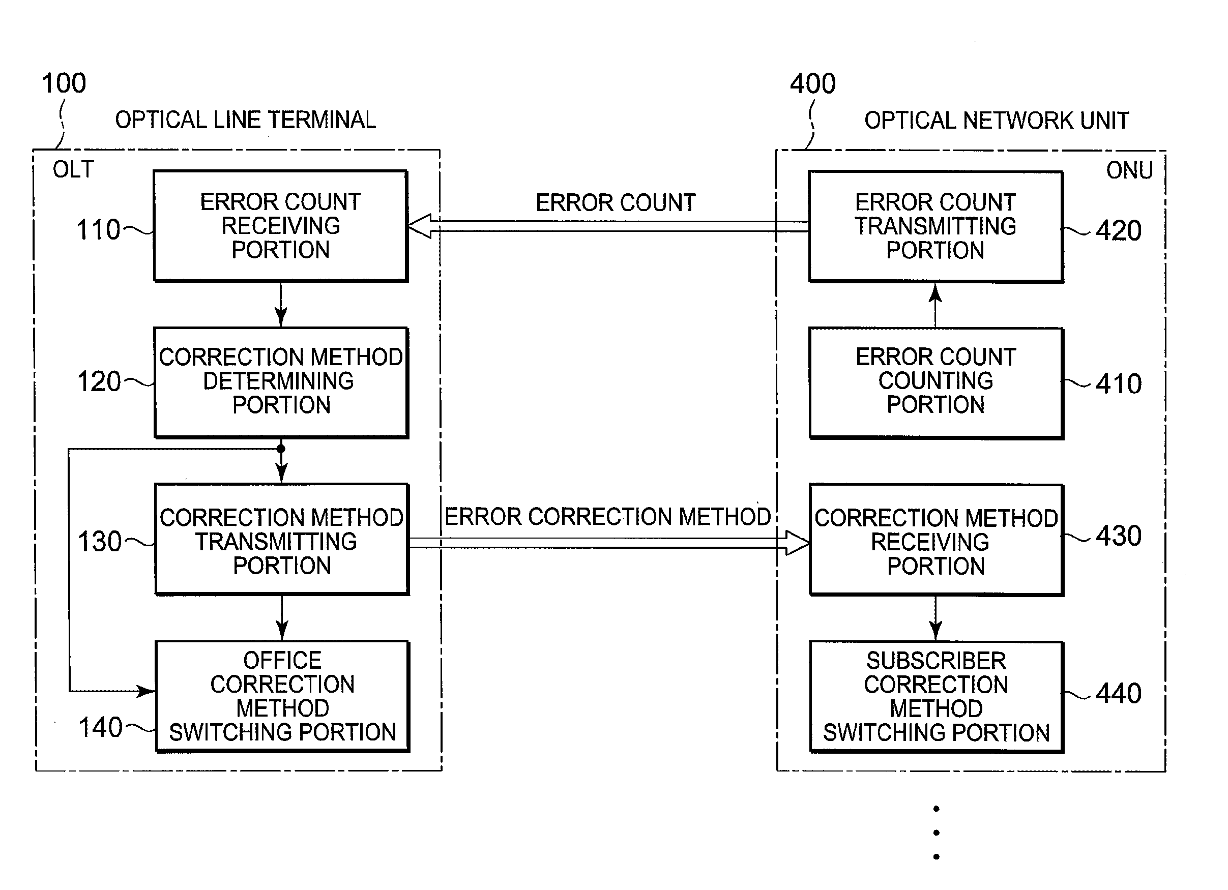
[0027]Referring to FIG. 3, the description will proceed to a passive optical network (PON) system according to a first exemplary embodiment of the present invention. The PON system is one of optical communications systems. The PON system comprises an optical line terminal (OLT) 100 and a plurality of optical network units (ONUs) 400. In FIG. 3, a specific one of the optical network units (ONUs) 400 alone is drown. The optical line terminal (OLT) 100 serves as an office terminating unit while each optical network unit (ONU) 400 serves as a subscriber terminating unit. The optical line terminal 100 is connected to the optical network units 400 through an optical transmissi...


PUM


Abstract

A subscriber terminating unit includes an error count counting portion counting an error count in a predetermined time range based on the number of corrections by an error correction function and an error count transmitting portion transmitting the error count to an office terminating unit. The office terminating unit includes an error count receiving portion receiving the error count from the subscriber terminating unit as a received error count and a correction method determining portion determining, based on the received error count, an error correction method or an error correction disuse which is used in the subscriber terminating unit.

Description

[0001]This application is based upon and claims the benefit of priority from Japanese patent application No. 2008-189699, filed on Jul. 23, 2008, the disclosure of which is incorporated herein in its entirety by reference.BACKGROUND OF THE INVENTION[0002]1. Technical Field[0003]This invention relates to an optical communications system such as a PON (Passive Optical Network) system, and more particularly, to an office terminating unit (OLT; Optical Line Terminal) and a subscriber terminating unit (ONU; Optical Network Unit) for use in the optical communications system.[0004]2. Background Art[0005]FIG. 1 shows structure of a general PON system. As shown in FIG. 1, the general PON system comprises an optical line terminal (OLT) 901, an optical transmission path 902, an optical coupler 903, and first through N-th optical network units (ONUs) 904-1, . . . , 904-N where N represents a positive integer which is not less than two. The first through the N-th optical network units (ONUs) 904...

Claims


Application Information

Patent Timeline
Patent Type & Authority Applications(United States)
IPC IPC(8): H04B10/08H04B10/2581H04L1/00H04L12/44
CPCH04L1/1671H04L1/1812H04B10/07H04B10/2507H04B10/2581
Inventor KANNO, YOSHINORISHIRAISHI, KENOGUSHI, SADAICHIRO
Owner NEC CORP
Why Eureka
Try Eureka