Sliding rack ratchet tensioner

a ratchet tensioner and sliding rack technology, applied in the direction of gearing, mechanical control devices, instruments, etc., can solve the problems of increasing the cost of manufacturing the piston, increasing the manufacturing cost, and subsequently inducing higher chain loads than desired, and achieve the effect of simplifying assembly

Inactive Publication Date: 2010-01-28
BORGWARNER INC
View PDF14 Cites 35 Cited by
  • Summary
  • Abstract
  • Description
  • Claims
  • Application Information

AI Technical Summary

Benefits of technology

[0009]The high-performance sliding rack ratchet tensioner is inexpensively manufactured. A rack having rack teeth is slidingly received in a rack slot on the side of the piston. The rack slot is preferably open-ended on the end facing the tensioner arm. The rack and piston are both received in a piston bore in the tensioner body. The rack length is preferably shorter than the rack slot length to provide backlash. A pawl mounted in a pawl bore perpendicular to the rack bore engages the rack. The open-ended rack slot allows the rack to be inserted after the piston during assembly. The rack and pawl preferably have shark fin-shaped teeth. The pawl preferably has dummy teeth to ensure that the load is shared by the center teeth.
[0016]In yet another embodiment, the method of assembling a ratchet tensioner includes the step of inserting a piston into a tensioner body with a piston bore open at one end and a pawl bore extending into the piston bore. The piston has an outer circumference slidably received in the piston bore and a rack slot axially extending and formed as part of the outer circumference. The rack slot has an open end at an outward end of the piston. The method includes the step of slidably inserting the rack into the rack slot after the step of inserting the piston, simplifying assembly due to uni-directional piston and rack insertion. The rack includes a plurality of rack teeth. The method preferably further includes the step of locating a pawl on the rack after the step of inserting the rack. The pawl is slidably received in the pawl bore. The pawl includes a plurality of pawl teeth.

Problems solved by technology

This greatly increases the expense of manufacturing the piston.
Upon initial release when the piston extends to tension the chain and comes to a hard stop, the rack may overshoot, thereby reducing the backlash of the tensioner arm and subsequently inducing higher chain loads than desired.
Additionally, the angle on the pawl bore increases manufacturing costs.

Method used


Image

  • Sliding rack ratchet tensioner
  • Sliding rack ratchet tensioner
  • Sliding rack ratchet tensioner

Examples


first embodiment

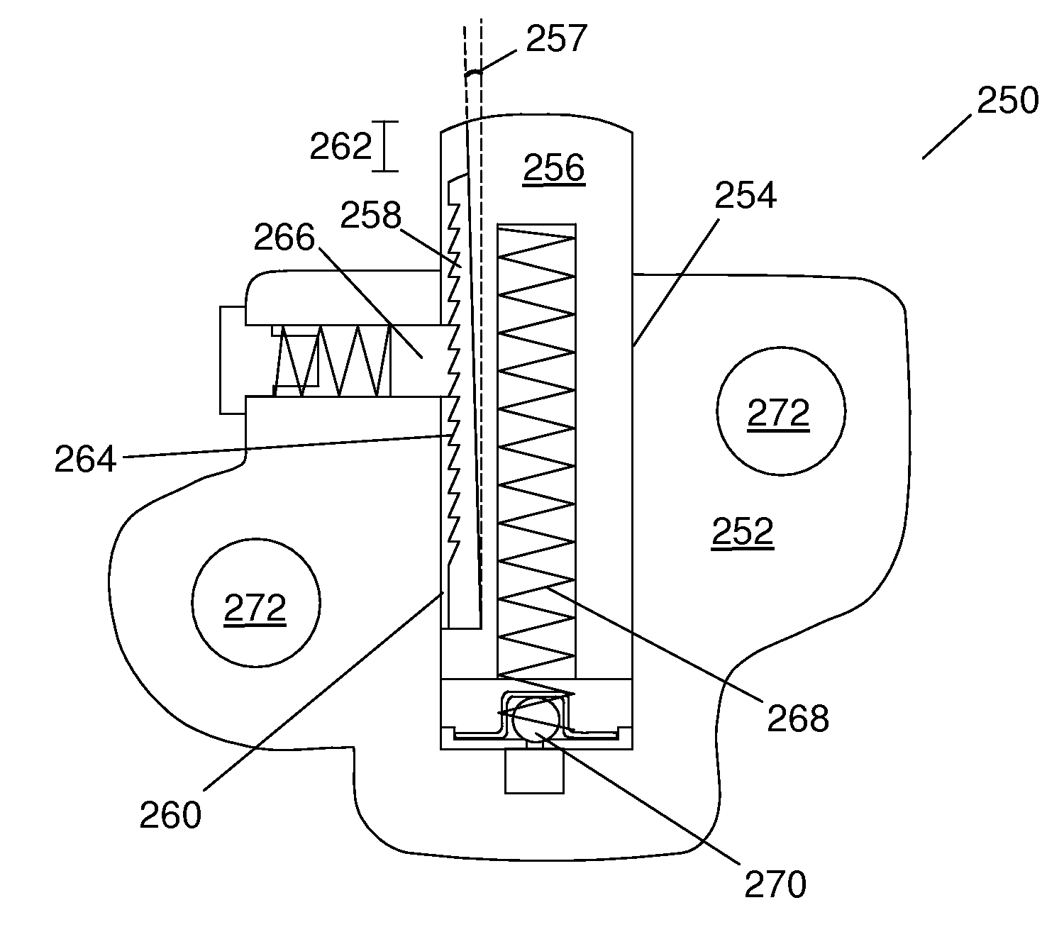
[0036]In the present invention, the rack and the piston are separate components. The simplified geometry of the rack part allows it to be manufactured as a powdered metal (PM) part. The rack sits in a rack slot of the piston. In the assembled tensioner, the rack is confined within the piston envelope such that the rack and piston both sit within the piston bore of the tensioner body, thereby eliminating the need for a rack bore. This provides greater flexibility to position the tensioner bolt holes in the absence of a rack bore and allows for a more compact design. The cylindrical piston is tooled to produce a rack slot parallel to the piston axis with the slot being open on the end facing the tensioner arm. In this embodiment, there is no need for a washer part on the rack nor is a piston shoulder feature necessary.

[0037]The open-ended slot provides several advantages over a closed-ended slot. First, the open-ended slot is more easily machined into the piston than a closed-ended sl...

second embodiment

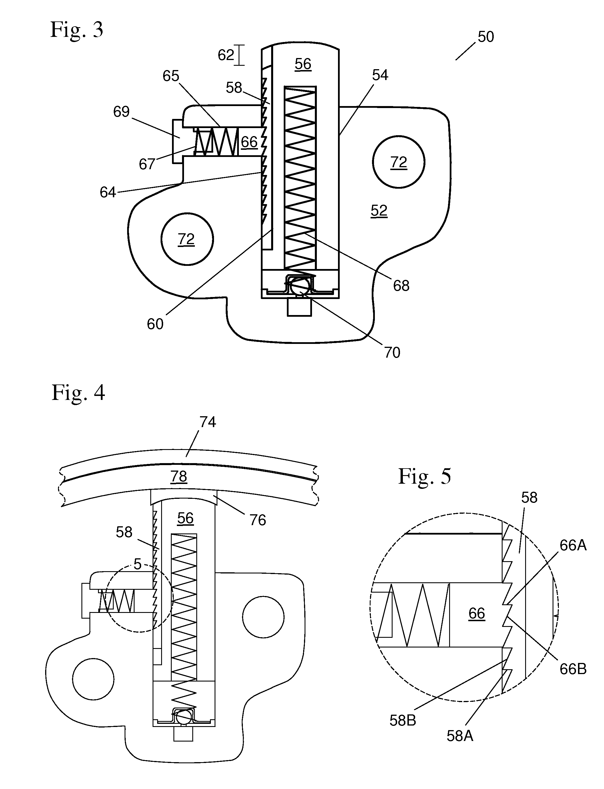
[0038]In the present invention, the pawl assembly for engaging the rack sits in a pawl bore perpendicular to the piston bore. Preferably the tensioner has a tooled ramp angle on the side of the pawl to retract the ratchet to an open position automatically and hold it open during reset. Preferably the reset hole and the shipping hole are integrated as one feature in the pawl assembly, further simplifying manufacture and assembly. The pawl preferably has both front and rear dummy teeth to ensure that the load is shared by the center teeth. The dummy teeth provide stability to the pawl, but they do not engage the vertical surfaces of the rack teeth. The vertical surface of a tooth, as used herein, refers to the flat surface on one side of the tooth which is parallel to the direction the tooth extends outward. The front dummy tooth acts as an anti-tipping surface.

[0039]A third embodiment of the present inventions combines the features of the first and second embodiments. In this embodim...

fourth embodiment

[0040]In a fourth embodiment, the rack slot and the rack are angled with respect to the piston bore such that the rack and rack slot taper toward the open end of the rack slot. The rack angle, which is the angle between the rack / piston interface and the axis of the piston, inhibits rack overextension by reducing rack momentum in the protruding direction and supplementing the pawl spring force increasing ratcheting resistance if the rack moves relative to the piston. The rack angle is preferably selected to prevent wedging of the rack between the piston and the wall of the piston bore when the piston moves in the retracting direction before the tensioner backlash provided by the difference between the length of the rack slot and the length of the rack is utilized.

[0041]A tensioner of the present invention has a relatively low rack mass, resulting in low inertial loads on the rack. The piston offers a smoother and more stable sliding interface for the rack. The rack and piston prefera...


PUM

PropertyMeasurementUnit
outer circumferenceaaaaaaaaaa
circumferenceaaaaaaaaaa
distanceaaaaaaaaaa

Abstract

The high-performance sliding rack ratchet tensioner is inexpensively manufactured. A rack having rack teeth is slidingly received in a rack slot on the side of the piston. The rack slot is preferably open-ended on the end facing the tensioner arm. The rack and piston are both received in a piston bore in the tensioner body. The rack length is preferably shorter than the rack slot length to provide backlash. A pawl mounted in a pawl bore perpendicular to the rack bore engages the rack. The open-ended rack slot allows the rack to be inserted after the piston during assembly. The rack and pawl preferably have shark fin-shaped teeth. The pawl preferably has dummy teeth to ensure that the load is shared by the center teeth.

Description

REFERENCE TO RELATED APPLICATIONS[0001]This application claims one or more inventions which were disclosed in Provisional Application No. 60 / 886,686, filed Jan. 26, 2007, entitled “SLIDING RACK RATCHET TENSIONER”. The benefit under 35 USC §119(e) of the United States provisional application is hereby claimed, and the aforementioned application is hereby incorporated herein by reference.BACKGROUND OF THE INVENTION[0002]1. Field of the Invention[0003]The invention pertains to the field of ratchet tensioners. More particularly, the invention pertains to a ratcheting mechanism for a ratchet tensioner.[0004]2. Description of Related Art[0005]Rack and pawl ratchet chain tensioners are known in the art. Known tensioners include separate rack versions and integral rack versions, where the rack is commonly formed integrally along the side of the piston. This greatly increases the expense of manufacturing the piston.[0006]A rack and washer hydraulic tensioner 10, as disclosed in U.S. Pat. Nos...

Claims


Application Information

Patent Timeline
Patent Type & Authority Applications(United States)
IPC IPC(8): F16H7/08G05G3/00B23P11/00
CPCF16H7/0836F16H7/0848F16H2007/0806Y10T29/49826F16H2007/0859Y10T74/2141F16H2007/0853F16H7/00F16H7/08
Inventor BARVE, ANAND ARUN
Owner BORGWARNER INC
Why Eureka
Try Eureka