KVM system

a keyboard and mouse technology, applied in the field of communication, can solve the problems of not meeting the needs of kvm administrators in large corporations, not easy to connect much more computers, and complicating the main board circuit of kvm switches

Inactive Publication Date: 2010-01-28
ATEN INT CO
View PDF9 Cites 28 Cited by
  • Summary
  • Abstract
  • Description
  • Claims
  • Application Information

AI Technical Summary

Benefits of technology

[0009]To solve the foregoing disadvantages in the conventional techniques, an objective of the present invention is to transmit single-ended video signals in a keyboard-video-mouse (KVM) system directly rather than encode / decode video signals or differential video signals.

Problems solved by technology

Since the size of 15-pin VGA connector is too large, it is not easy to connect much more computers.
This may not serve the needs of IT administrators in large corporations.
The 3-in-1 D-sub 15 cable provides not only five wires for transmitting video signals but also another five wires for transmitting KB data signals, KB clock signals, KB power signals, MS data signals, and MS clock signals corresponsively, and thus complicate the main board circuit of KVM switch.
Furthermore, the 3-in-1 D-sub 15 cable does not transmit USB storage data signals and audio signals.
However, one of the disadvantages of KVM system utilizing CAT 5 based KVM device communication is that a video encoder circuit and a video decoder circuit are needed.
Therefore, video encoder and decoder circuits not only increase the cost of modules and KVM switches, but also increase the response time of video signal to result in a bad performance.

Method used


Image

  • KVM system
  • KVM system
  • KVM system

Examples


first embodiment

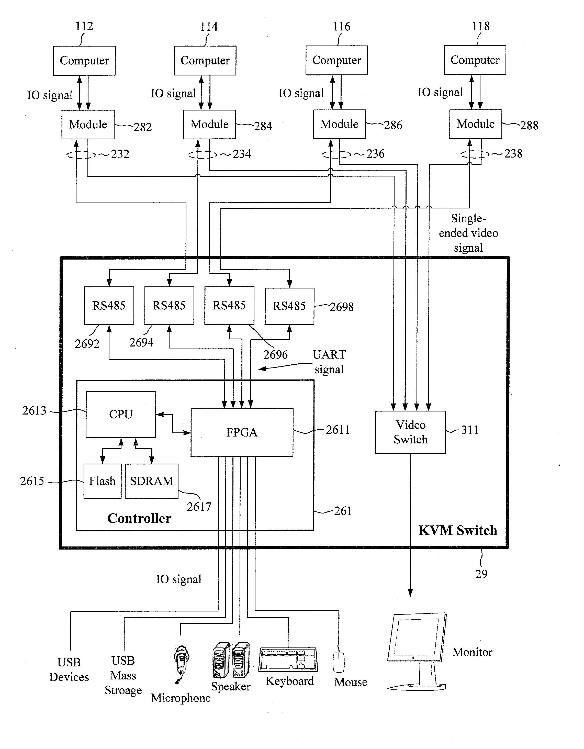
[0035]Please refer to FIGS. 3a and 3b. a KVM system in accordance with the present invention is illustrated. As shown in FIG. 3a, there are 4 computers, computer 112, computer 114, computer 116 and computer 118, coupled to the KVM switch 29. Each computer is accompanied with a module. One module couples one computer to the KVM switch 29. The computer 112 is accompanied with a module 282, the computer 114 with a module 284, the computer 116 with a module 286, and the computer 118 with a module 288. The KVM switch 29 has a video switch 311 to switch to one of the computers and to route a single-ended video signal from the one of the computers to a monitor for display. The KVM switch 29 has a controller 261 to manage and process an IO signal so as to select which computer the IO signal is to be transmitted to. The IO signal may come from a keyboard, a mouse, a speaker, a microphone, an USB mass storage, and / or other USB devices etc. The controller 261 comprises a field-programmable gat...

second embodiment

[0038]Please refer to FIG. 4. The second embodiment in accordance with the present invention is implemented with a KVM extender. The KVM extender, which allows access to a computer 11 from a console device in the distance, comprises a local unit 48 and a remote unit 49. The local unit 48 is coupled with the computer 11 to transmit a signal-ended video signal and an IO signal to the remote unit 49 via a signal cable 43. The signal cable 43 has a first RJ-45 connector at its first end for connecting the local unit 48 and a second RJ-45 connector at its second end for connecting the remote unit 49. The local unit 48 comprises a FPGA 4511, a CPU 4513, a Flash memory 4515, a SDRAM 4517 and a RS-485 transceiver 4590, and the remote unit 49 comprises a FPGA 4611, a CPU 4613, a Flash memory 4615, a SDRAM 4617 and a RS-485 transceiver 4690. The local unit 48 further comprises a video buffer 4118 for buffering the single-ended video signal so as the remote unit has a video buffer 4119. The CP...

third embodiment

[0039]Please refer to FIG. 5. The third embodiment in accordance with the present invention is implemented with a matrix KVM system, which allows multiple users control computers simultaneously and independently. The computers can be connected through a combination of multiple matrix KVM switches. As shown in FIG. 5, a computer 11 is coupled to console devices (KB / MS / monitor / USB / Audio) via a first module 58, a matrix KVM switch 59, and a second module 50. The first module 58 comprises a FPGA 5511, a CPU 5513, a Flash memory 5515, a SDRAM 5517, a RS-485 transceiver 5590 and a video buffer 5118, the matrix KVM switch 59 comprises a FPGA 5611, a CPU 5613, a Flash memory 5615, a SDRAM 5617, numbers of RS-485 transceiver, e.g. a RS-485 converter 5670, 5680, 5690, and 5699, and a video buffer 5119, and the second module 50 comprises a FPGA 5011, a CPU 5013, a Flash memory 5015, a SDRAM 5017, a RS-485 transceiver 5090 and a video buffer 5110. The matrix KVM switch 59 has a video matrix 511...


PUM


Abstract

A keyboard-video-mouse (KVM) system is disclosed. The KVM system comprises a module, a KVM switch and a signal cable. The module transmits a single-ended video signal from a computer, converts a universal asynchronous receiver/transmitter (UART) signal to an input/output (IO) signal, and transmits the IO signal to the computer. The KVM switch receives the single-ended video signal from the module and outputs the UART signal to the module. The signal cable transmits the single-ended video signal from the module to the KVM switch and transmits the UART signal from the KVM switch to the first module.

Description

TECHNICAL FIELD OF THE INVENTION[0001]The present invention relates to a keyboard-video-mouse (KVM) system, and more particularly, to communication in the KVM system.BACKGROUND OF THE INVENTION[0002]Communication between a KVM switch and a module (e.g. a dongle) is an important part for designing a KVM system. It has to take many aspects into consideration, such as signal cable, connector, signal converter, and transmitting distance etc. For a well designed KVM system, video signals, keyboard (KB) signals, and mouse (MS) signals can be transmitted therebetween properly.[0003]Here provided two main conventional techniques, D-sub 15 (15-pin VGA connector) based KVM device communication and category 5 (CAT 5) based KVM device communication. Generally, a KVM system utilizing D-sub 15 based KVM device communication is called an analog KVM system in which a common 15-pin VGA connector is often used. Since the size of 15-pin VGA connector is too large, it is not easy to connect much more c...

Claims


Application Information

Patent Timeline
Patent Type & Authority Applications(United States)
IPC IPC(8): G06F13/38
CPCG06F3/023G06F3/038G09G2370/24G06F3/1423G09G2370/047G06F3/14
Inventor LIU, YI-LI
Owner ATEN INT CO
Why Eureka
Try Eureka