Jig for manufacturing components of aerodynes and wing turbines and manufacturing process for these components

Inactive Publication Date: 2010-02-04
TORRES MARTINEZ MANUEL
View PDF11 Cites 28 Cited by
  • Summary
  • Abstract
  • Description
  • Claims
  • Application Information

AI Technical Summary

Benefits of technology

[0007]According to the present invention, a jig for manufacturing this type of component, as well as a manufacturing process by means of using said jig is proposed, all of which allows simplifying the manufacture of these components, allowing the automation and the demolding of aerodynamic components with a complex geometry according to repetitive manufacturing processes which allow achieving suitable and constant quality conditions in the finally obtained product.
[0008]To that end, the invention proposes a jig having collapsible parts through elastic hinging means; the position of which parts can be regulated by means of positioning actuators, which provides the jig with a flexible character allowing the automation of the manufacturing proc

Problems solved by technology

The previously mentioned spars are fundamentally based on a U-shaped configuration changing in height in the different longitudinal sections of said spars, while at the same time they have variations of the a

Method used


Image

  • Jig for manufacturing components of aerodynes and wing turbines and manufacturing process for these components
  • Jig for manufacturing components of aerodynes and wing turbines and manufacturing process for these components
  • Jig for manufacturing components of aerodynes and wing turbines and manufacturing process for these components

Examples


Embodiment Construction

[0025]The present invention relates to a jig designed for manufacturing components, preferably of aerodynes and wind turbines, and to the actual manufacturing process for such components, which is developed by means of using said jig.

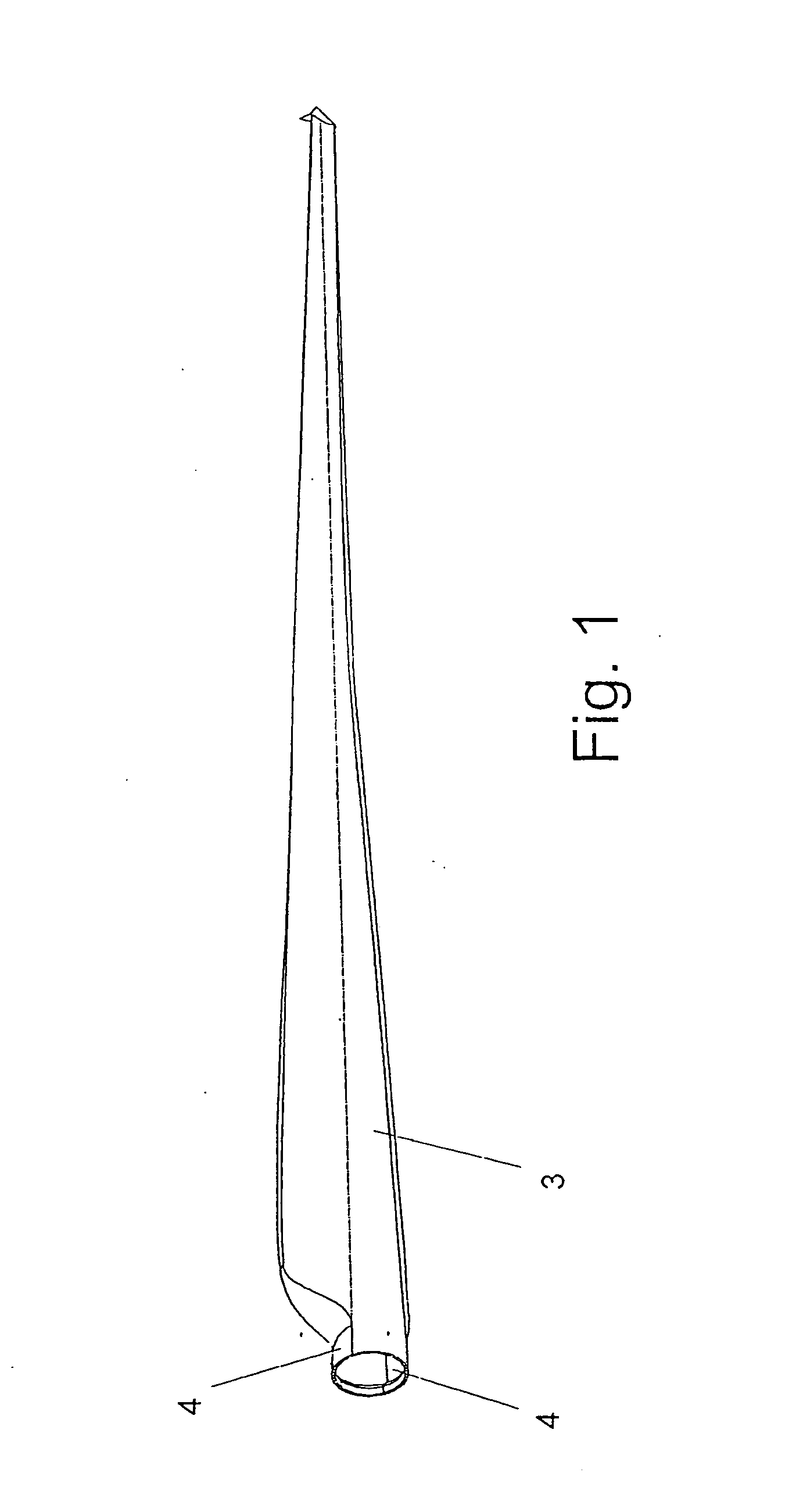
[0026]FIG. 1 shows, according to a possible non-limiting practical embodiment, the blade of a wind turbine as a possible non-limiting example of components of aerodynes and wind turbines.

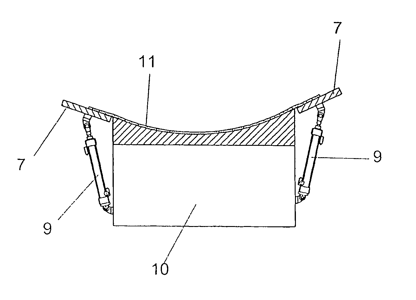
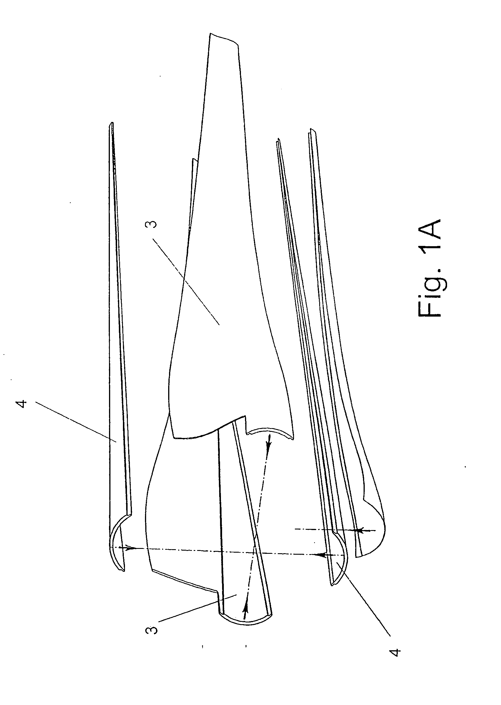
[0027]In the case of the wings and of the stabilizers of airplanes, in their root, the torsion box is parallelepiped and allows the connection on the central box of the airplane fuselage. In the case of the blades of wind turbines, as can be seen in FIGS. 1 and 1A, the root of the blades is cylindrical, allowing a connection on the circular bearing of the pitch of the wind turbine.

[0028]There are different methods and ways for manufacturing these blades about which the applicant has various patents. According to the example depicted in FIGS. 1 and 1A, the cylindrical ro...


PUM


Abstract

The invention relates to a jig for manufacturing components of aerodynes and wind turbines and a manufacturing process for these components, the jig comprising a base (10), on which at least one rigid part (7) like a flange is arranged in the upper edge of at least one of the sides, which rigid part is connected to the base (10) through an elastic hinge (8), which can driven to pivot between a raised closed position and a lowered open position, for the molding and demolding of the components to be manufactured by means of incorporating fiber strip layers on the surface that they determine between the base (10) and the flange or flanges (7).

Description

STATE OF THE ART[0001]Composite materials, formed by two or more materials and based on the use of carbon fibers, glass fibers, etc., provide a series of advantages including that of providing a high strength with minimum weight, therefore they are increasingly used in different industrial sectors, such as the aeronautical sector, shipbuilding sector, renewable energy sector, civil construction sector, etc.[0002]In the aeronautical sector, such composite materials are used to form the aerodynamic profiles of the wings and the stabilizers of aerodynes; whereas in the renewable energy sector, such composite materials are used to manufacture the blades, hubs, shafts and towers of wind turbines, all of this as the most common but non-limiting applications.OBJECT OF THE INVENTION[0003]The object of the present invention is especially designed for its application in the manufacture of components of aerodynes and wind turbines, but this must be understood in a limiting sense either, since ...

Claims


Application Information

Patent Timeline
IPC IPC(8): B23P15/02B25B27/14
CPCB29C33/00B29C33/308B29C70/443Y10T29/53961B29L2031/082B29L2031/085Y10T29/49336B29C70/54Y02P70/50
Inventor TORRES MARTINEZ, MANUEL
Owner TORRES MARTINEZ MANUEL
Why Eureka
Try Eureka