Power Conversion Apparatus and Electric Vehicle

a technology of power conversion apparatus and electric vehicle, which is applied in the directions of electric propulsion mounting, safety/protection circuit, transportation and packaging, etc., can solve the problems of increasing the dimensional size and manufacturing cost of the apparatus, and achieve the effect of reducing the inductance of the wiring

Active Publication Date: 2010-02-04
HITACHI ASTEMO LTD
View PDF15 Cites 173 Cited by
  • Summary
  • Abstract
  • Description
  • Claims
  • Application Information

AI Technical Summary

Benefits of technology

[0005]According to the present invention, therefore, the power conversion apparatus can reduce the inductance of the wiring for the connection between the capacitor module and each power module while cooling down the power modules, the capacitor module, and the wiring board.

Problems solved by technology

And this has caused the apparatus to expand in height of the space above the power module and its assembling work to be complicated, resulting in rising of the dimensional sizes and manufacturing cost of the apparatus.

Method used


Image

  • Power Conversion Apparatus and Electric Vehicle
  • Power Conversion Apparatus and Electric Vehicle
  • Power Conversion Apparatus and Electric Vehicle

Examples


Embodiment Construction

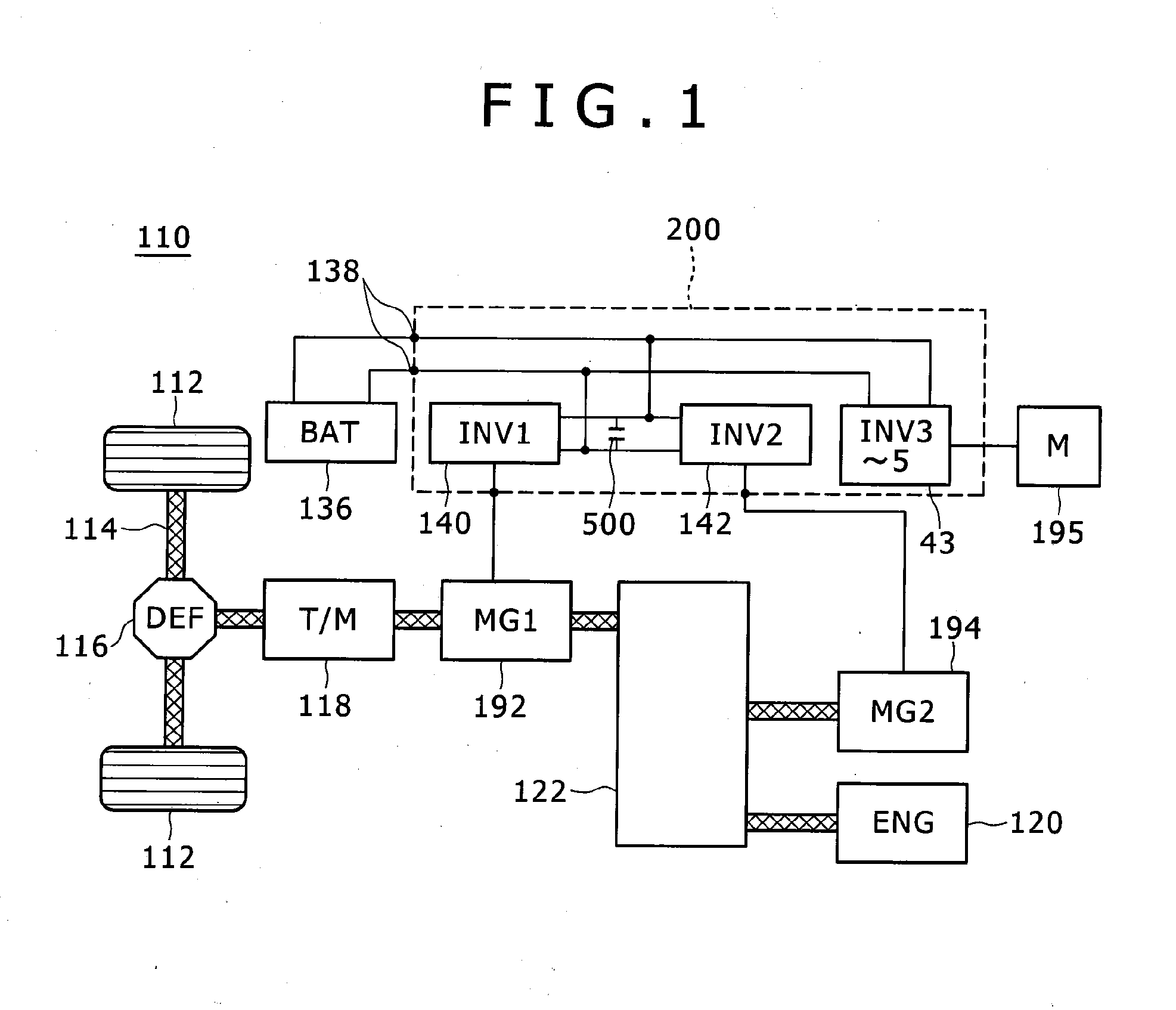
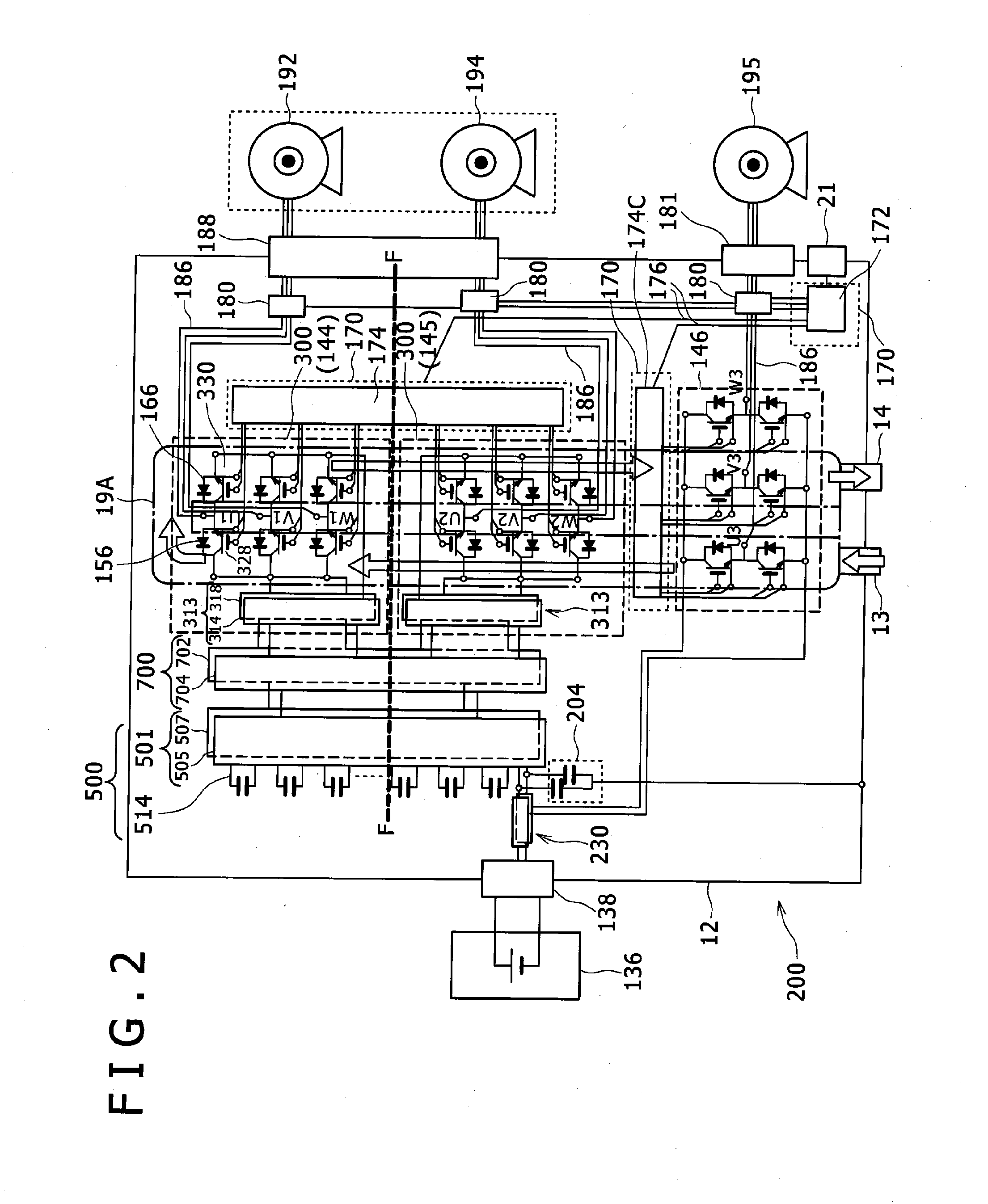
[0048]Hereunder, there will be described the preferred embodiments of the present invention in detail with respect to a power conversion apparatus with reference to the accompanying drawings. The power conversion apparatus can apply to any of hybrid vehicles and completely electric-power-driven vehicles. Here, it is premised that the power conversion apparatus is typically applied to a hybrid vehicle and a control system configuration and a circuit configuration of the apparatus will be described with reference to FIGS. 1 and 2.

[0049]In a preferred embodiment of the present invention, the power conversion apparatus is employed typically for an on-vehicle motor system, particularly a vehicle driving inverter device usable under very severe ambient and environmental driving conditions. The vehicle driving inverter device is provided for a vehicle driving motor system assumed as a controller that controls the driving of the motor used for driving the subject vehicle. The inverter devic...


PUM


Abstract

The metallic case of a power conversion apparatus includes a casing having a side wall, as well as an upper case and a lower case, a first area being formed between a cooling jacket provided at the inner periphery of the side wall and the lower case, the metal base plate dividing the first area between the cooling jacket and the upper case into a lower side second area and an upper side third area, first and second power modules being fastened to a top surface and a capacitor module being provided in the first area, driving circuits that drive inverter circuits of the power modules respectively being provided in the second area, and a control circuit that controls the driver circuits being provided in the third area.

Description

FIELD OF THE INVENTION[0001]The present invention relates to a power conversion apparatus that includes a power module provided with a built-in inverter circuit, as well as an electric vehicle that employs the power conversion apparatus.BACKGROUND OF THE INVENTION[0002]Each of well-known conventional power conversion apparatuses employs a structure that includes two power modules, on each of which are disposed control boards used for a capacitor module, as well as for those two power modules in layers (e.g., refer to JP-A No. 2008-29117).SUMMARY OF THE INVENTION[0003]In any of those conventional power conversion apparatuses, the capacitor, the bus bar, and the power module control board mounted above the power module respectively are all heat generators, so that the apparatus is required to be structured so as to cool down those components. In order to meet such a requirement, the apparatus provides a cooling board in each hierarchical layer to transmit the heat generated by each of...

Claims


Application Information

Patent Timeline
Patent Type & Authority Applications(United States)
IPC IPC(8): B60K1/00H05K7/20B60L50/16
CPCB60L11/00H05K7/20927H02M7/003H05K7/20H01L2224/48091H01L2224/48472H01L2224/49111H02J7/0029H05K7/209H05K7/02H01L2924/1305H01L2924/13055H01L2924/13091B60L2200/26H01L2924/00014H01L2924/00B60L50/00H01L2224/48227H05K7/14322H05K7/14329H05K5/0026H05K7/1432
Inventor NAKATSU, KINYASUSUKI, HIDEYONISHIKIMI, FUSANORIMATSUO, TAKESHISATOU, TOSHIYA
Owner HITACHI ASTEMO LTD
Why Eureka
Try Eureka