Suspension system for vehicle

a suspension system and vehicle technology, applied in the direction of bicycle equipment, instruments, transportation items, etc., can solve the problem of serious problems such as the heat generation of electric motors as power sources

Active Publication Date: 2010-02-04
KYB CORP +1
View PDF3 Cites 35 Cited by
  • Summary
  • Abstract
  • Description
  • Claims
  • Application Information

AI Technical Summary

Benefits of technology

[0003]Because the electromagnetic actuator is constantly kept operated during a running of the vehicle, heat generation of an electric motor as a power source is a serious problem that the electromagnetic actuator conventionally has been experienced. The system disclosed in the above-indicated Patent Document 1 deals with such a problem by reducing electric power consumption owing to a reduction in an electric current supplied to the actuator where an average consumption amount of the electric power within a certain time exceeds a predetermined upper limit value. The utility of the suspension system equipped with the electromagnetic actuator can be improved by thus taking some measures to deal with the heat generation of the electric motor. The present invention has been developed in the light of the situations described above. It is therefore an object of the invention to improve the utility of the suspension system equipped with the electromagnetic actuator.
[0004]To achieve the object indicated above, a suspension system for a vehicle according to the present invention is characterized in that the suspension system is configured to be capable of executing a control for avoiding a state in which an operation of an electric motor as a power source of an electromagnetic actuator is kept halted at a certain operational position while the motor is generating a motor force.

Problems solved by technology

Because the electromagnetic actuator is constantly kept operated during a running of the vehicle, heat generation of an electric motor as a power source is a serious problem that the electromagnetic actuator conventionally has been experienced.

Method used


Image

  • Suspension system for vehicle
  • Suspension system for vehicle
  • Suspension system for vehicle

Examples


first embodiment

(A) First Embodiment

1. Structure and Function of Suspension System

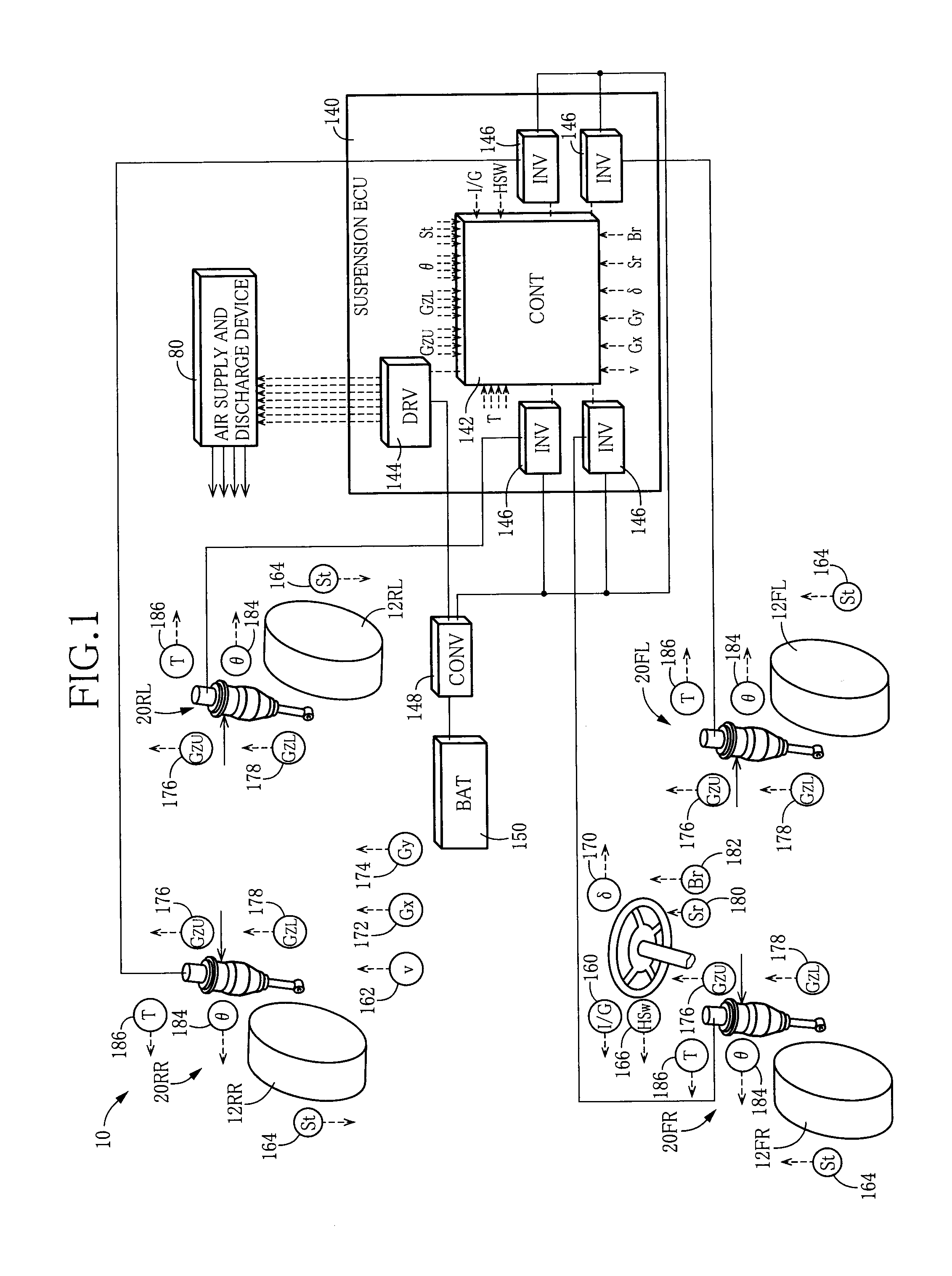
[0094]FIG. 1 schematically shows a suspension system 10 for a vehicle according to a first embodiment. The suspension system 10 includes four independent suspension apparatus which respectively correspond to four wheels 12 (i.e., a front left wheel, a front right wheel, a rear left wheel, and a rear right wheel). Each of the suspension apparatus includes a spring•absorber Assy 20 in which a suspension spring and a shock absorber are united. The four wheels 12 and the four spring•absorber Assys 20 are collectively referred to as the wheel 12 and the spring•absorber Assy 20, respectively. Where it is necessary to distinguish the four wheels 12 from each other and to distinguish the four spring•absorber Assys 20 form each other, there are attached suffixes “FL”, “FR”, “RL”, and “RR” respectively indicating the front left wheel, the front right wheel, the rear left wheel, and the rear right wheel.

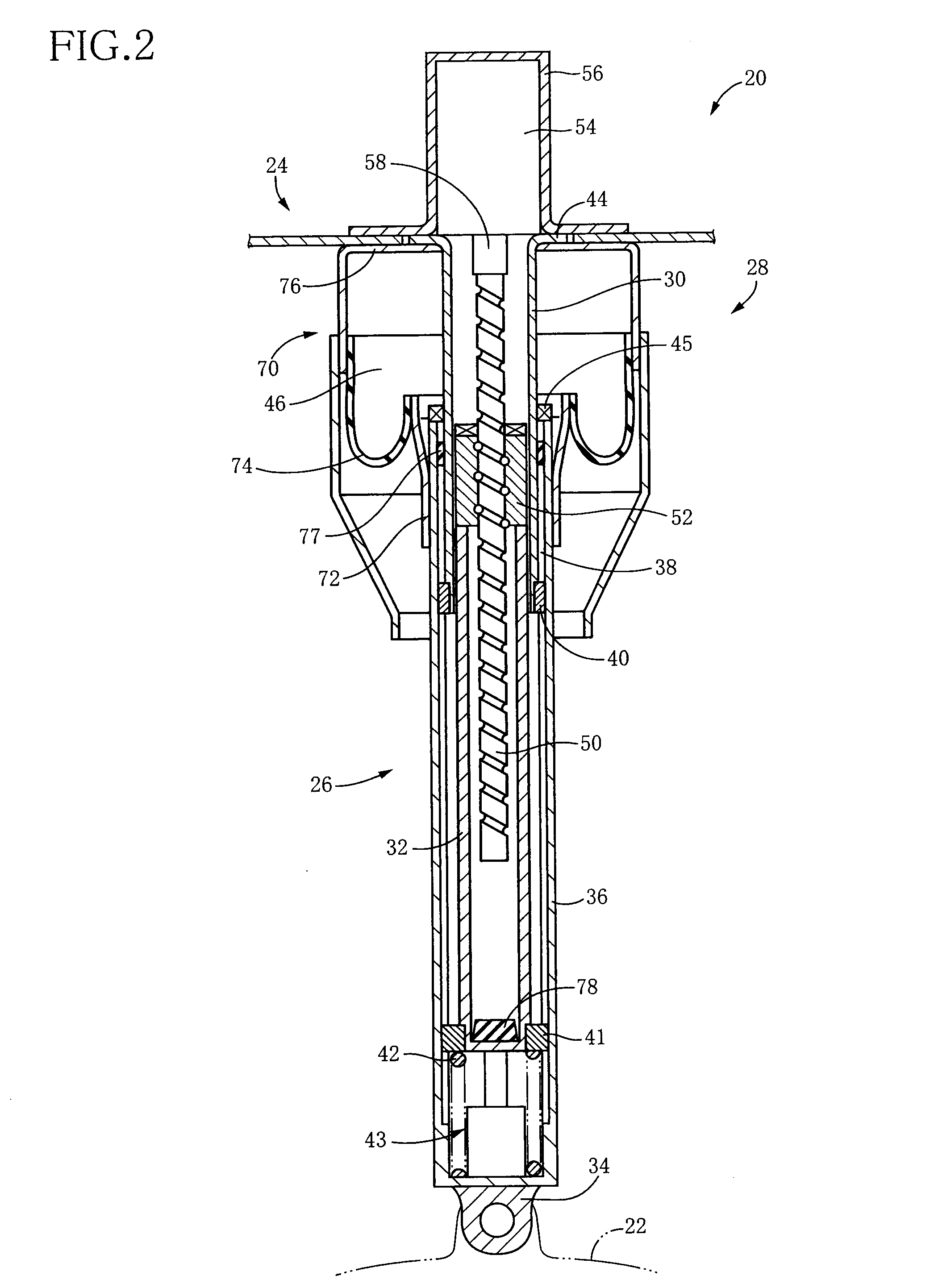
[0095]As shown in FIG. 2,...

second embodiment

(B) Second Embodiment

[0137]A suspension system for a vehicle according to a second embodiment is identical in hardware structure with the system in the illustrated first embodiment. In the following explanation, therefore, the same reference numerals as used in the first embodiment are used to identify the corresponding components having the same function as in the first embodiment, and a detailed explanation of which is dispensed with. The system of the second embodiment differs from the system of the first embodiment in the control by the ECU. Accordingly, the control by the ECU according to the present embodiment will be hereinafter explained.

1. Control of Actuator

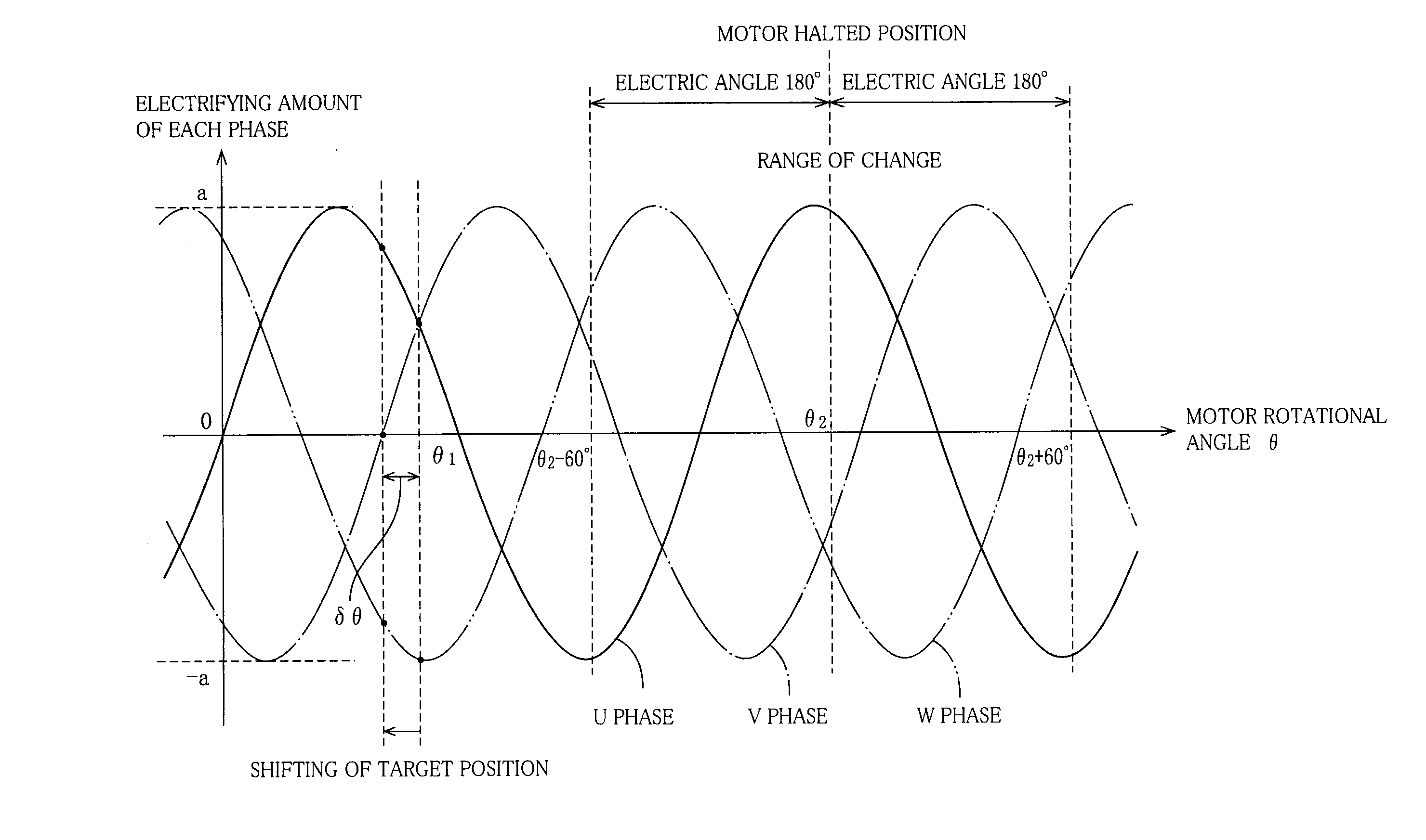
[0138]The present embodiment differs from the illustrated first embodiment in a control of the actuator 26 by the suspension ECU 140. In the present suspension system 10, the actuator forces of the actuators 26 in the respective spring•absorber Assys 20 are controlled independently of each other for executing the vibrat...


PUM


Abstract

It is an object of the invention to provide a suspension system configured to execute a control for avoiding a state in which an operation of an electric motor which is a power source of an electromagnetic actuator is kept halted at a certain operational position while the motor is generating a motor force. Where a target rotational position of the motor becomes equal to a specific operational position (e.g., a rotational position at which an electrifying current amount of one phase reaches a peak value), a control for shifting the target rotational position by δθ is executed. Where the rotational position of the motor is kept located at the certain position for a time period longer than a prescribed time, a control for changing the rotational position of the motor is executed. According to the present suspension system, it is possible to suppress imbalance in heat generation in the motor and to thereby reduce a load to be applied to the motor. Accordingly, a suspension system with high utility is realized.

Description

TECHNICAL FIELD[0001]The present invention relates to a suspension system including an electromagnetic actuator configured to generate a force by which a body and a wheel of a vehicle are moved toward and away from each other in a vertical direction.BACKGROUND ART[0002]In recent years, there has been developed, as a suspension system for a vehicle, a so-called electromagnetic suspension system including an electromagnetic actuator configured to generate a force by which a body and a wheel of a vehicle are moved toward and away from each other in a vertical direction. For instance, the following Patent Document 1 discloses such an electromagnetic suspension system. The disclosed suspension system is expected to be a high-performance suspension system in view of an advantage that it is possible to easily realize a suspension characteristic based on a so-called skyhook theory.Patent Document 1 JP-A-2003-42224DISCLOSURE OF THE INVENTION(A) Summary of the Invention[0003]Because the elect...

Claims


Application Information

Patent Timeline
Patent Type & Authority Applications(United States)
IPC IPC(8): B60G17/00F16F15/02F16F15/03
CPCB60G15/08F16F2232/06B60G17/0157B60G17/018B60G17/0521B60G17/06B60G2202/152B60G2202/314B60G2202/42B60G2204/126B60G2204/419B60G2204/4232B60G2204/62B60G2400/0511B60G2400/0516B60G2400/102B60G2400/104B60G2400/106B60G2400/204B60G2400/252B60G2400/33B60G2400/382B60G2400/39B60G2400/41B60G2400/716B60G2400/73B60G2500/201B60G2500/2021B60G2500/203B60G2500/30B60G2600/02B60G2600/07B60G2600/08B60G2600/182B60G2800/012B60G2800/014B60G2800/162B60G2800/80B60G2800/9122B60G2800/914B60G2800/916F16F2232/04B60G17/0155
Inventor INOUE, HIROFUMIWATANABE, HIDESHIKONDO, TAKUHIRO
Owner KYB CORP
Why Eureka
Try Eureka