

Balanced Amplifying Device Having a Bypass Branch
a technology of balanced amplifying device and bypass branch, which is applied in the direction of gated amplifiers, amplifiers, semiconductor devices/discharge tubes, etc., can solve the problems of increased insertion loss, limiting the performance of switches, and always controversial implementation of switches at the input of amplifiers, so as to achieve positive influence on losses
- Summary
- Abstract
- Description
- Claims
- Application Information
AI Technical Summary
Benefits of technology
Problems solved by technology
Method used
Image

Examples
first embodiment
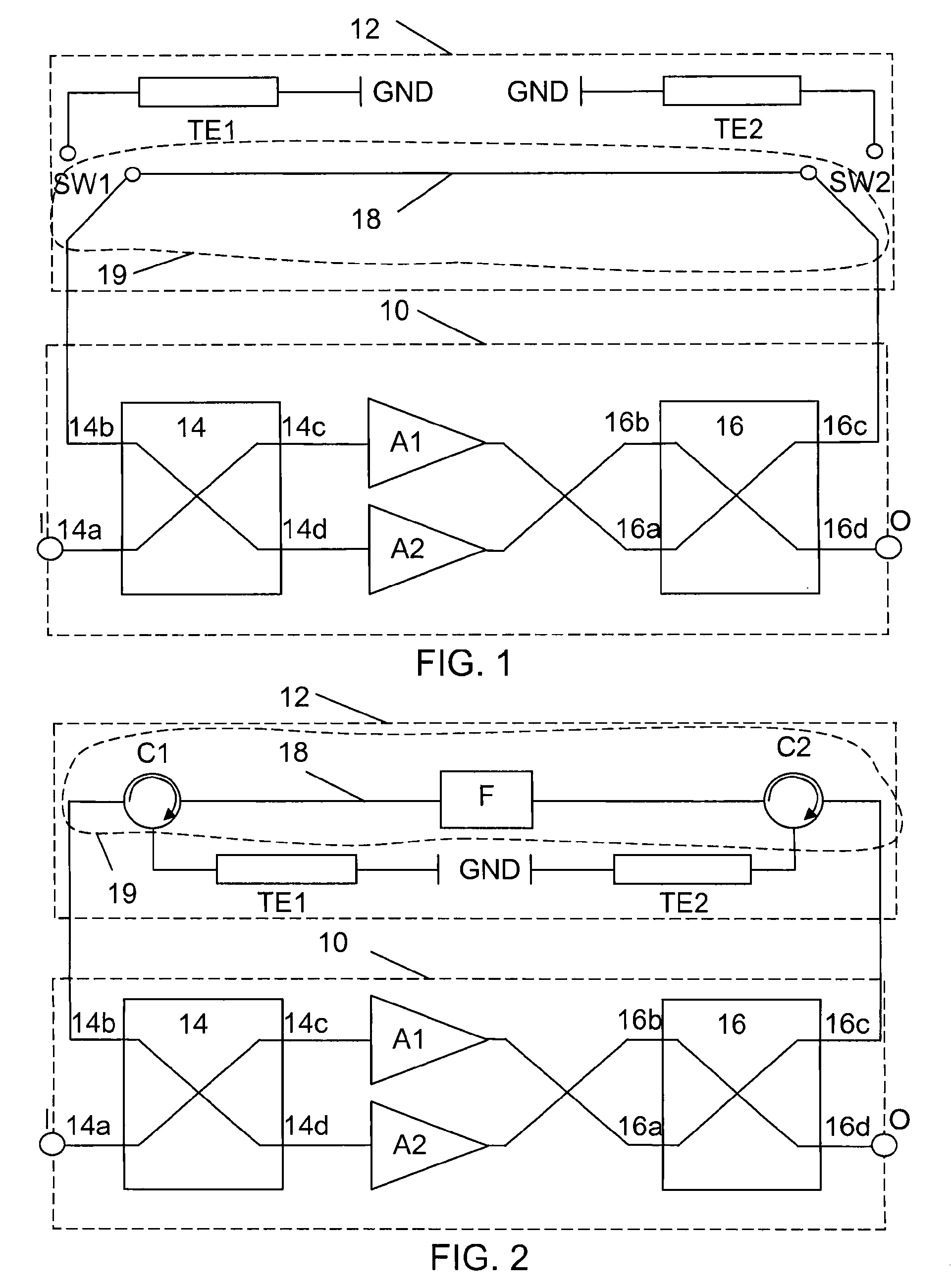
[0034]a balanced amplifying device is shown in a circuit diagram in FIG. 1. The balanced amplifying device, which is a low noise amplifier, includes an amplifying section 10 and a bypass and isolating section 12, both shown as dashed boxes. The amplifying section 10 includes a first coupling / splitting unit 14 in the form of an input hybrid coupler 14. The input hybrid coupler 14 has four ports, where a first port 14a acts as an input port and also as the input I of the amplifying device, a second port 14b acts as an isolated port in normal mode and is therefore connected to the bypass and isolating section 12. A third port 14c of the input hybrid coupler 14 is connected to the input of a first amplifier A1, while a fourth port 14d of the input hybrid coupler 14 is connected to the input of a second amplifier A2. The amplifiers A1 and A2 include necessary matching and biasing (not shown) and are provided with power (also not shown). The output of the first amplifier A1 is connected t...
second embodiment
[0045]This second embodiment has a number of advantages. The design requires no switches at all and the bypass section has no active components, which means that bypass operation may be provided even if there is no power. Since there are no active components, the solution is robust and confident with good LTBF (life time between failures).
[0046]Also this second embodiment may be varied. It can include more circulators in order to provide further reverse isolation. It may also include fewer circulators. In its simplest form it only includes one circulator. It should also be realised that the filter may be omitted.
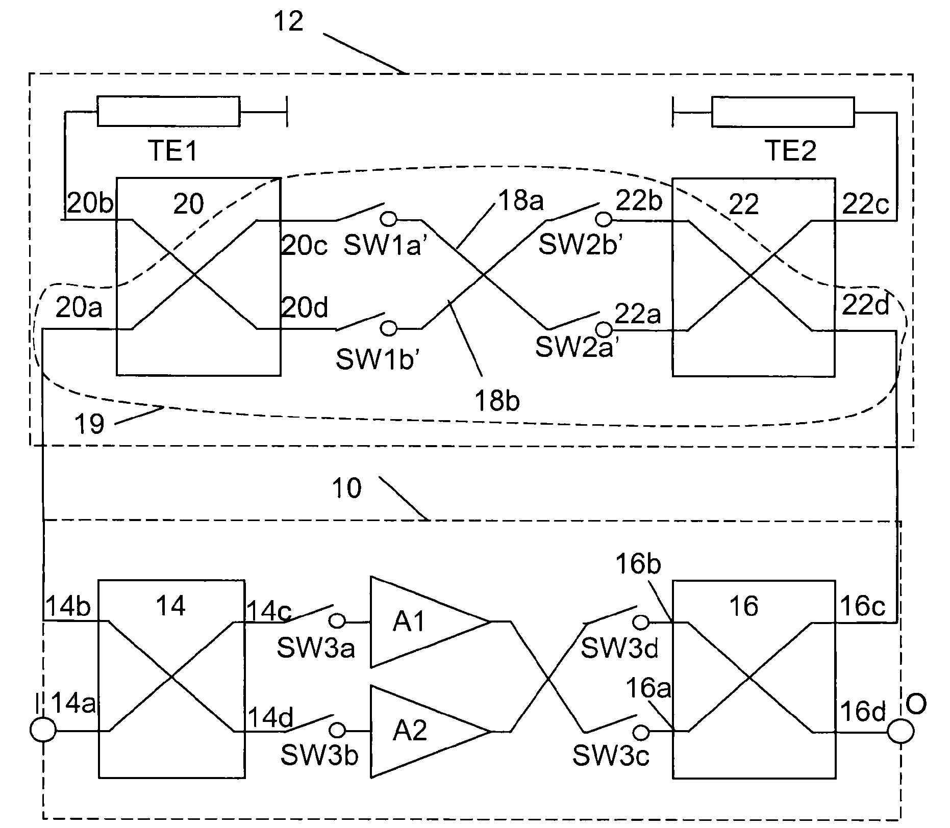
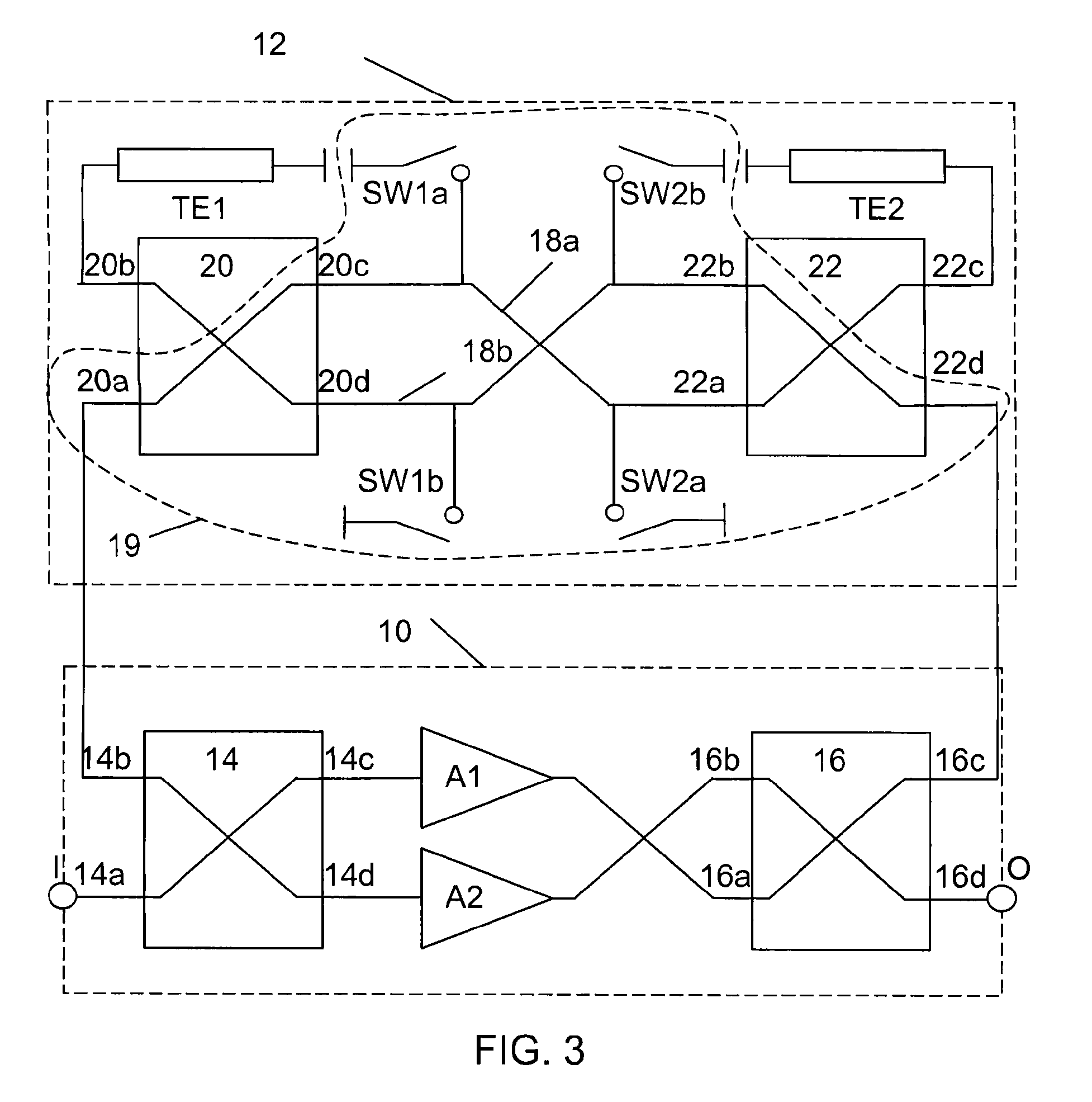
[0047]FIG. 3 shows a circuit diagram of a balanced amplifying device according to a third embodiment of the present invention. The amplifying section 10 of this third embodiment is identical to the amplifying section of the first embodiment. Here only the bypass and isolating section 12 differs. In this embodiment the isolation is again provided through a first and second te...
fourth embodiment
[0051]The advantage of this fourth embodiment is that it improves the nonlinear performance of the balanced amplifying device in the bypass mode.
[0052]There are a number of variations that are possible also with the third and fourth embodiments. The bypass switches may be connected in either of the two described ways in both embodiments. One pair of bypass switches may also be omitted, and then preferably the output bypass switches. The fourth port of the second bypass hybrid coupler may be connected to the fourth port of the output hybrid coupler. However, in this case the second termination element will be connected to the third port of the output hybrid coupler and a further termination element be connected between the third port of the second bypass hybrid coupler and ground. The performance enhancement switches of the fourth embodiment may also be connected in the same way as the bypass switches in the third embodiment. The performance enhancement switches may furthermore be in...
PUM
 Abstract
Description
Claims
Application Information