Safe and high-brightness LED lamp

a led lamp, high-bright technology, applied in the direction of transportation and packaging, semiconductor devices of light sources, light and heating apparatus, etc., can solve the problems of shortening the service life and serious electric consumption, and achieve the effect of improving heat radiation efficiency, prolonging the service life and increasing brightness

Inactive Publication Date: 2010-02-04
HUANG YAO HUI +1
View PDF6 Cites 89 Cited by
  • Summary
  • Abstract
  • Description
  • Claims
  • Application Information

AI Technical Summary

Benefits of technology

[0006]The present invention relates to a safe and high-brightness LED lamp, which consists of a lampshade, a bulb mounting base, a LED module and a circuit board, where after combining said lampshade and said bulb mounting base, it will be able to construct an inner space, which is allowable to store said LED module and circuit board, wherein, the said LED module consists of a heat-radiating block, an LED lamp panel and a reflective wall, where said LED lamp panel can be flat nestled up against said heat-radiating block at one end, moreover, such reflective wall can be coupled with the LED lamp so that the reflective wall is able to partition the said inner space into one light source refractive space and one flowing space for airflow thereof. Furthermore, there is an electrical fan installed outside the thermal conductivity pillar of said heat-radiating block. Thereby, while LED light is firstly being refracted and diffused via the reflective wall into the light source refractive space in lampshade it will become more uniform, and again while it is secondly being refracted and diffused by the light diffusing layer of said lampshade, then it not only will become an uniform light source with higher brightness, but also it will improve the heat radiation efficiency, and thus, resulting in a longer service life for such LED lamp while utilizing the said flowing space for airflow to guide the heat energy blown by the electric fan directly.
[0007]The primary objective of the present invention lies in providing a kind of bulb structure that utilize the reflective wall installed at circumference of a LED lamp to firstly refract and diffuse LED light into a lampshade, and then such LED light will secondly be refracted and diffused, through light source refractive space, by the diffusing and reflecting layer positioned at inner layer of said lampshade in order to generate an uniform LED light along with high brightness.
[0008]The secondary objective of the present invention is to provide a kind of bulb that utilizes a heat-radiating block to contact with LED lamp panel to absorbing a great deal of heat energy, and also utilizing a heat-radiating fan to directly guide heat energy with a flowing space for airflow, so that heat energy will be rapidly diffused into atmosphere via heat radiating hole of bulb mounting base and hence prolonging the service life of said bulb by the method of decreasing the temperature of LED module thereof.
[0009]Another objective of the present invention is to provide a kind of bulb that cab be applied to the existing production equipments, so that it can reduce the production costs with a wider field of application.
[0010]Again, one more objective of the present invention is to provide a single LED lamp with a higher illumination efficiency as well as lower consumption of electricity.

Problems solved by technology

However, while using LED bulb as a light source, its lightness could be limited due to the insufficient quantity of light bulbs, but if using too many light bulbs, then the electricity consumption will become a serious problem in addition to the high temperature during operating period which can even decreasing the lightness of LED lamp and furthermore shortening the service life of such LED lamp consequently.

Method used


Image

  • Safe and high-brightness LED lamp
  • Safe and high-brightness LED lamp
  • Safe and high-brightness LED lamp

Examples


Embodiment Construction

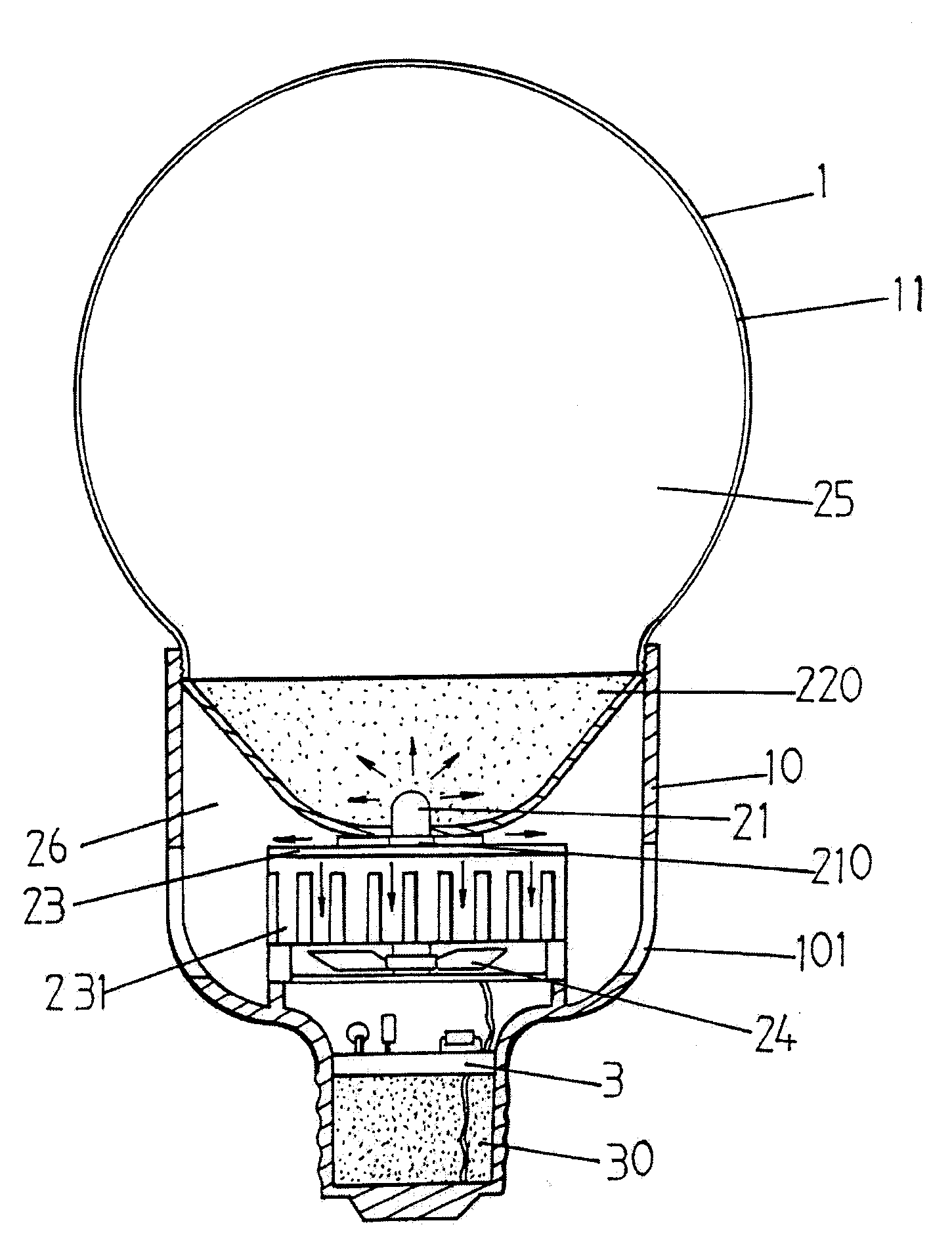
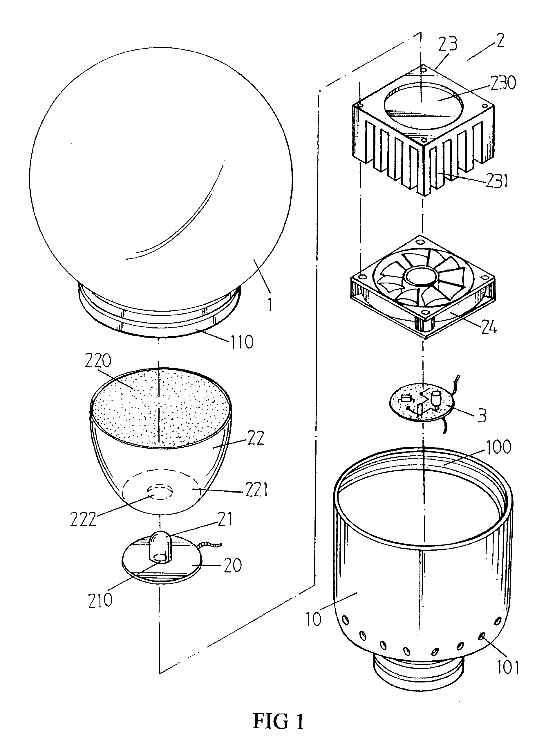
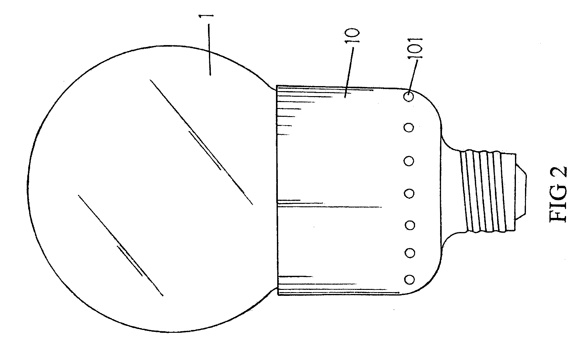
[0021]With reference to FIG. 1, 2, and 3 respectively, wherein, the preferred embodiment of the present invention is being represented with a bulb structure, which primarily consists of one lampshade 1, one bulb mounting base 10, one LED module 2 and one circuit board 31, wherein, the lampshade 1 has a hollow structure of shade body with an opening, where its inner layer is being adhered to a light diffusing layer 11, and the outer edge of opening of said lampshade has been constructed as a threaded portion 110 which can be coupled together with internal threads 100 positioned at opening of bulb mounting base 10 and constructing an inner space thereof. The said inner space can store both said LED module 2 and one circuit board 3, wherein, said LED module 2 consists of LED lamp panel 20, reflective wall 22, heat-radiating block 23, and heat-radiating fan 24; moreover, the said LED lamp panel 20 is installed with a LED lamp 21, and the end-contact 210 of said LED lamp 21 is being flat...


PUM

PropertyMeasurementUnit
brightnessaaaaaaaaaa
heat-radiatingaaaaaaaaaa
electrically conductiveaaaaaaaaaa

Abstract

A safe and high-brightness LED lamp consists of a lampshade, a bulb mounting base, an LED module and a circuit board. The lampshade and bulb mounting base construct an inner space, which is allowable to store said LED module; the LED module consists of a heat-radiating block, an LED lamp panel and a reflective wall, where such LED lamp panel can be flat nestled up against the heat-radiating block at one end. Moreover, such reflective wall can be coupled with the LED lamp so that the said inner space can be partitioned into one light source refractive space and one flowing space for airflow thereof. Furthermore, an electrical fan is installed outside the heat-radiating block. Thereby, while light is being refracted and diffused via reflective wall into the light source refractive space in lampshade, it will then be refracted and diffused once more, and under this circumstance, not only the light will become more uniform with higher brightness, but also it will improve the heat radiation efficiency, and thus, resulting in a longer service life for such LED lamp while utilizing the said flowing space for airflow to guide the air blown by the fan.

Description

BACKGROUND OF THE INVENTION[0001]1. Field of the Invention[0002]The present invention relates generally to a safe and high-brightness LED lamp, consisting of one lampshade, one bulb mounting base, one LED module and one circuit board, where the said lampshade and said bulb mounting base is constructing an inner space, which is allowable to store said LED module after assembly.[0003]2. The Prior Arts[0004]LED has several advantages, such as, energy-saving, longer service life, mercury-free, high color regeneration etc. as well as environmental protection, moreover, it even has a very high illuminating uniformity and sufficient light flux, therefore, it can be extensively applied to various fields, for instance: Traffic signals, large advertizing board, flashlight, indoor illumination etc.[0005]However, while using LED bulb as a light source, its lightness could be limited due to the insufficient quantity of light bulbs, but if using too many light bulbs, then the electricity consumpt...

Claims


Application Information

Patent Timeline
Patent Type & Authority Applications(United States)
IPC IPC(8): F21V7/00F21V29/02
CPCF21K9/135F21V29/02F21Y2101/02F21V3/04F21V29/83F21V7/22F21V17/12F21V29/677F21V29/763F21V7/06F21K9/232F21Y2115/10F21V7/24F21V7/28
Inventor HUANG, YAO HUICHEN, GUAN MING
Owner HUANG YAO HUI
Why Eureka
Try Eureka