Network Protection Switching Mechanisms and Methods of Network Protection

a network protection and switching mechanism technology, applied in transmission monitoring/testing/fault-measurement systems, lasers, transmissions, etc., can solve the problems of high cost, significant number of disruptions and outages, and difficulty in designing networks automatically protected against multiple worst-case fiber breaks, so as to facilitate protection against multiple network failures and increase the overall network reliability and availability.

Active Publication Date: 2010-02-04
HUBERSUHNER POLATIS LTD
View PDF4 Cites 21 Cited by
  • Summary
  • Abstract
  • Description
  • Claims
  • Application Information

AI Technical Summary

Benefits of technology

[0017]This configuration is particularly advantageous because it facilitates protection against multiple network failures since the protection paths may also be monitored after they are provisioned and the traffic automatically switched to another protection path in a pool of paths if a subsequent fiber failure occurs in the protection path. This consequently further increases overall network reliability and availability.

Problems solved by technology

Fiber cuts, equipment faults and degradations cause a significant number of disruptions and outages.
As businesses and consumers become increasingly intolerant of network failures, downtime can be very expensive to carriers due to both lost revenue and tarnished images.
Designing networks that are automatically protected against multiple worst-case fiber breaks can be difficult and expensive.
As a result, many network protection schemes typically only provide automatic protection against single fiber faults.
Major disasters, like earthquakes and hurricanes, can often cause multiple fiber breaks in a network.

Method used


Image

  • Network Protection Switching Mechanisms and Methods of Network Protection
  • Network Protection Switching Mechanisms and Methods of Network Protection
  • Network Protection Switching Mechanisms and Methods of Network Protection

Examples


Embodiment Construction

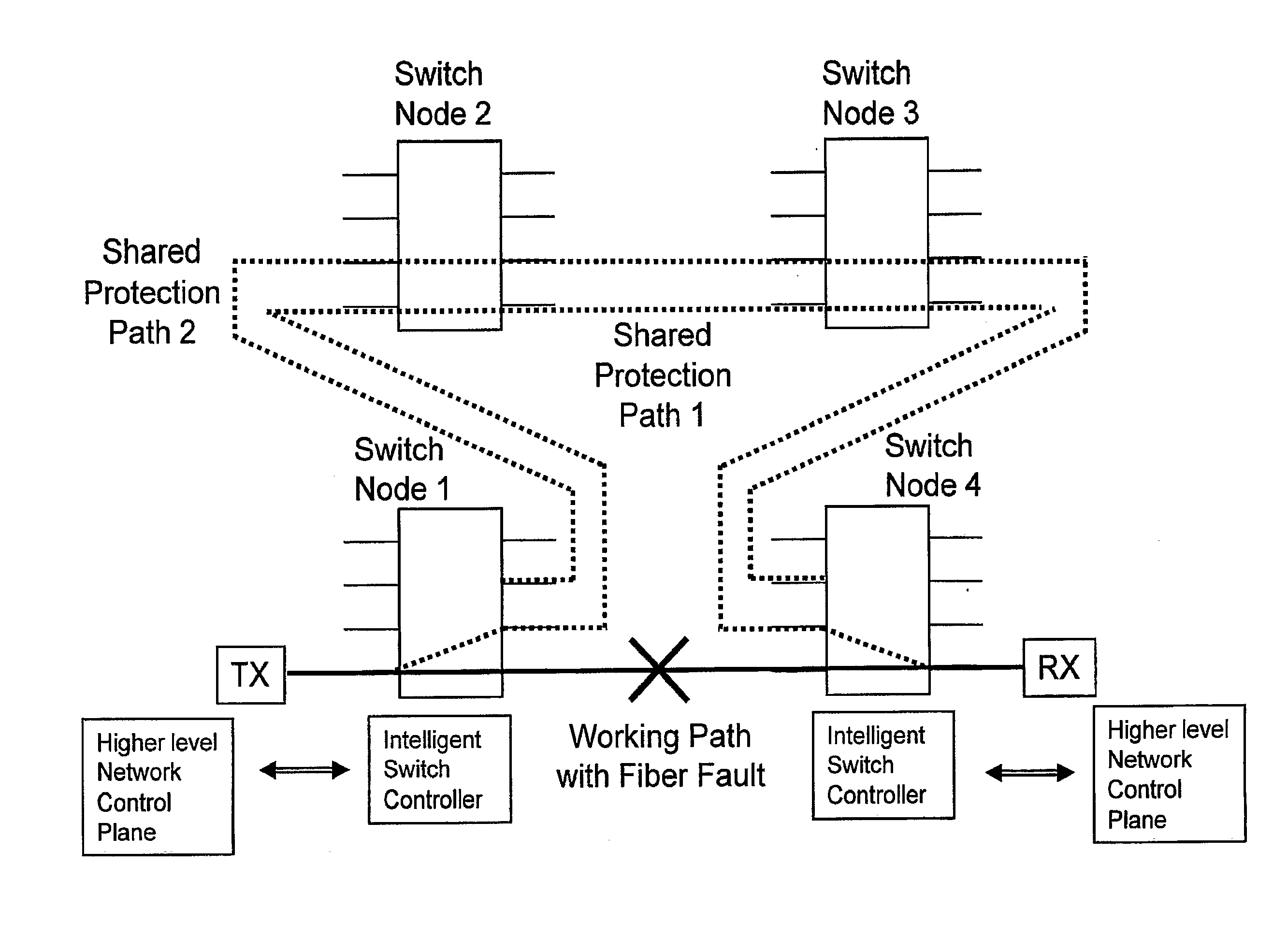
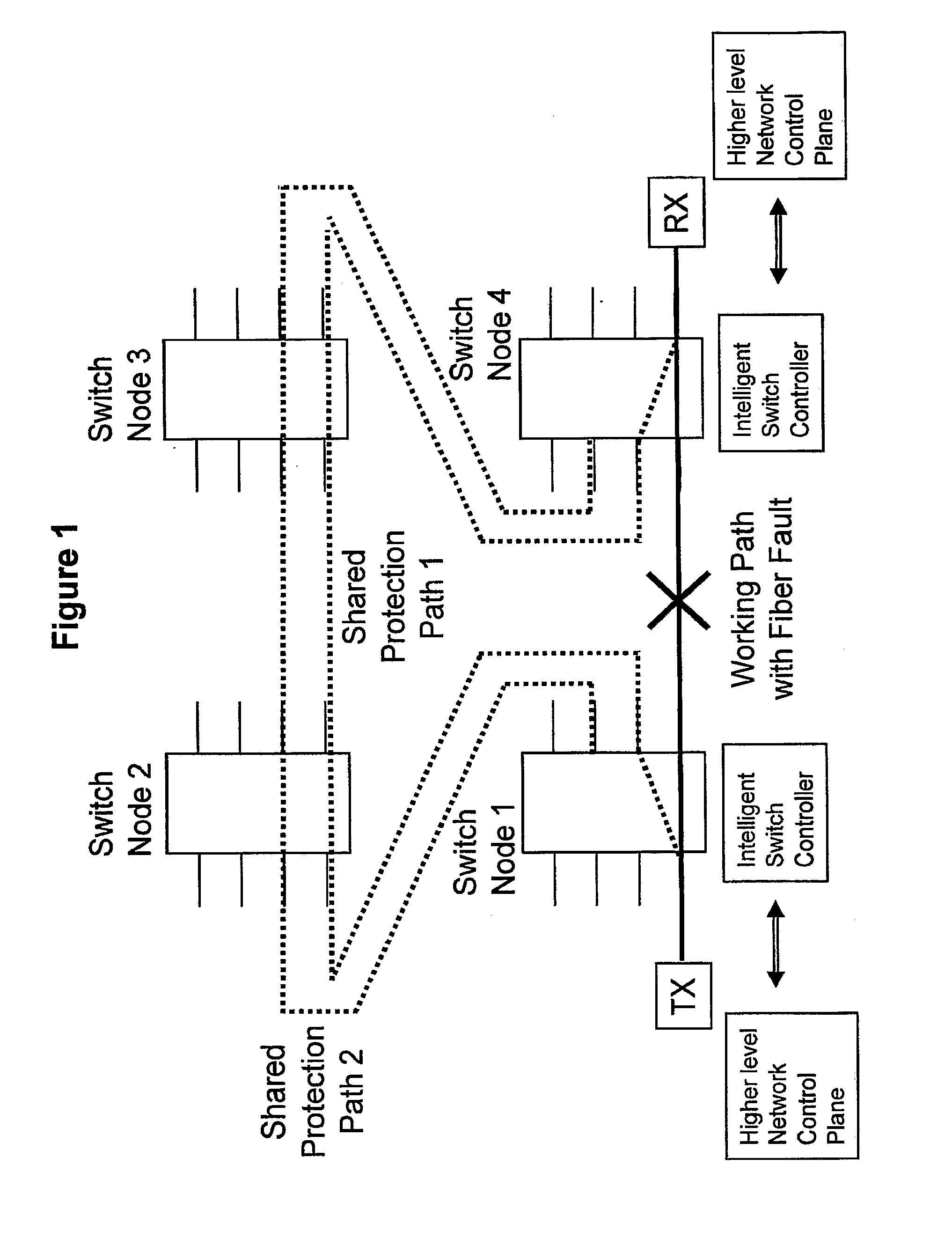
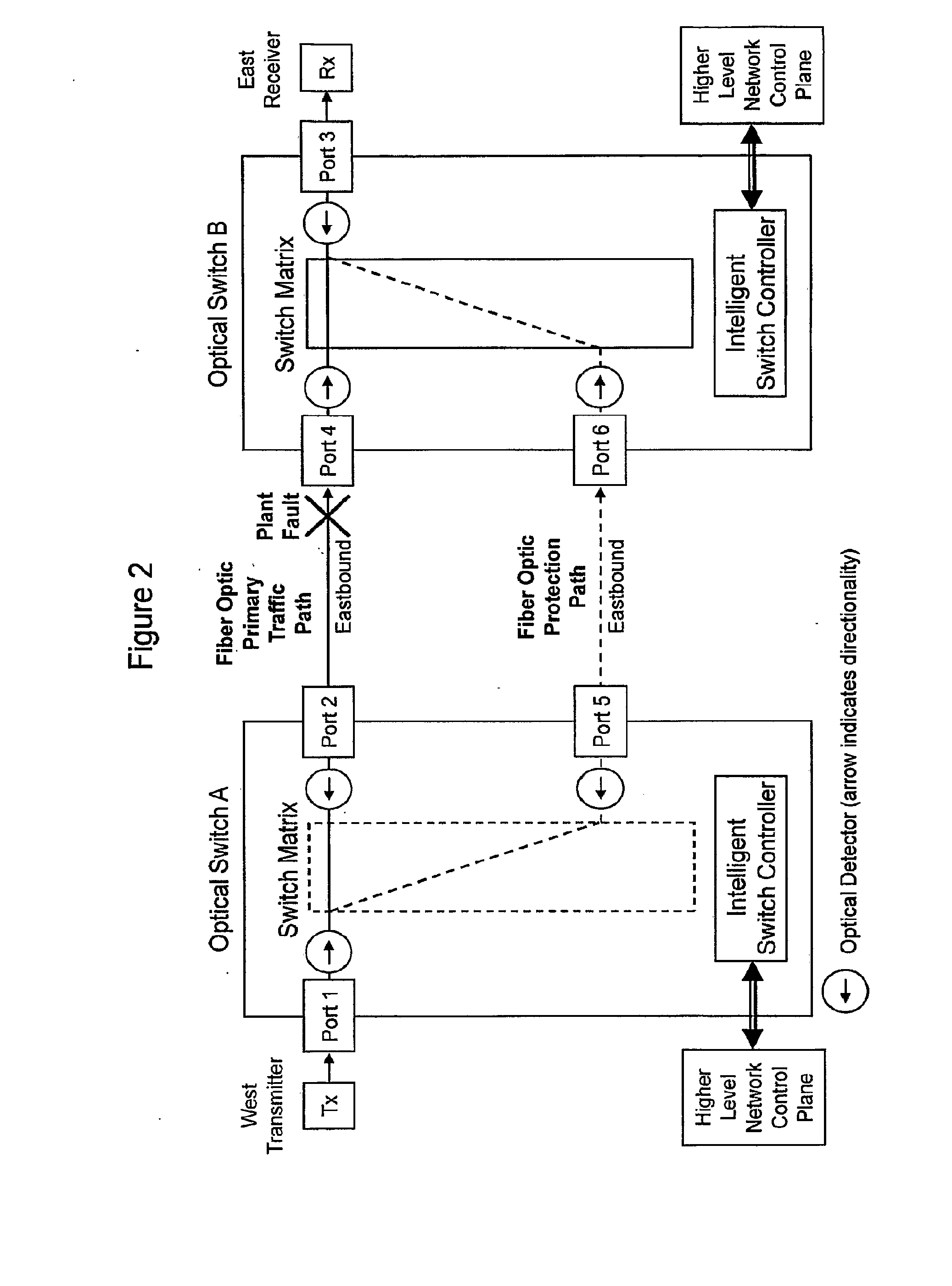
[0034]Embodiments of this invention increase the speed of fault detection and network protection switching by having intelligent optical switches with optical power detectors that can locally detect faults in the optical line. The switching controller operates without the switching being a result from switch to switch physical layer optical communication and without complicated overhead framing as required by prior art systems. Embodiments can also improve fiber utilization by allowing working lines to share a pool of protection paths.

[0035]The “shared pool” concept can be extended to the difficult task of protecting a network against multiple fiber breaks by simply monitoring through detectors such as optical power detectors the protection paths in the same way as the working paths after they are provisioned. This allows the traffic-carrying protection paths to be protected by the remaining resources of the shared pool. If the network experiences a second fiber break on either a pr...


PUM


Abstract

A network protection switching mechanism comprises a plurality of optical switches located at a plurality of nodes; a plurality of optical communication paths between said switches; switch based fault detectors located as part of at least two switches which generate detection results representative of the identification of a fault; switch based controllers located as part of said at least two switches; and internal switch-communication means between said fault detectors and said controllers which facilitate the transmission of detection results from said fault detectors to said controllers; wherein said controllers directly cause switching to an alternative optical communication path dependent upon the receipt of said detection results; whereby autonomous switch based protection without dependence on either inter-switch control communication or higher level network control communication is achieved.

Description

FIELD OF THE INVENTION[0001]The invention relates to network protection switching mechanisms and methods of network protection.BACKGROUND OF THE INVENTION[0002]Fiber cuts, equipment faults and degradations cause a significant number of disruptions and outages. As businesses and consumers become increasingly intolerant of network failures, downtime can be very expensive to carriers due to both lost revenue and tarnished images. As a result, carriers continually search for better ways to protect networks against such fiber faults and reduce costs by more efficient use of protection bandwidth.[0003]Existing protection switching systems usually involves higher level communications or signaling between nodes in the network using complex framed overhead channels or packet communications.[0004]Designing networks that are automatically protected against multiple worst-case fiber breaks can be difficult and expensive. As a result, many network protection schemes typically only provide automa...

Claims


Application Information

Patent Timeline
Patent Type & Authority Applications(United States)
IPC IPC(8): H04B10/00H04L69/40
CPCH04J14/0227H04J14/0279H04Q2011/0081H04J14/0291H04Q11/0062H04J14/0283
Inventor LEWIS, DAVID OWENJENSEN, RICHARD ANDREW
Owner HUBERSUHNER POLATIS LTD
Why Eureka
Try Eureka