Medical imaging apparatus

a medical imaging and apparatus technology, applied in the field of medical imaging apparatus, can solve the problems of low detection capability of tissue specific nature (tissue properties), difficult detection of tumor mass, and difficulty in finding calcification

Inactive Publication Date: 2010-02-04
FUJIFILM CORP
View PDF3 Cites 37 Cited by
  • Summary
  • Abstract
  • Description
  • Claims
  • Application Information

AI Technical Summary

Benefits of technology

[0015]The present invention has been achieved in view of the above-mentioned problems. A purpose of the present invention is, in a medical imaging apparatus for imaging mammary gland and breast while compressing the breast with a compression plate, to keep the posture of an ultrasonic probe relative to the compression plate constant and stabilize the moving motion of the ultrasonic probe.
[0017]According to the one aspect of the present invention, since the detecting means for detecting the location and / or the posture of the ultrasonic probe relative to the compression plate and the control means for controlling the location and / or the posture of the ultrasonic probe relative to the compression plate based on the detection result of the detecting means are provided, the posture of an ultrasonic probe relative to the compression plate can be kept constant and the moving motion of the ultrasonic probe can be stabilized.

Problems solved by technology

Radiation images obtained by X-ray imaging (X-ray mammography) of breasts for breast cancer diagnoses are useful for finding calcification as a precursor of mass and cancer, but finding calcification may be difficult depending on mammary gland density or the like of an object to be inspected.
However, the X-ray imaging has a disadvantage that detection capability of specific natures of tissues (tissue properties) is low.
Further, in an X-ray image, mammary glands are expressed in homogeneous soft tissue density, and thus, the detection of tumor mass is difficult in the case where mammary glands have developed (so-called, “dense breast”) as is the case of adolescent to premenopausal women.
On this account, even when a tumor mass is found, it is difficult to grasp information on the location, size, and so on of the tumor mass in the depth direction.
However, ultrasonic imaging examination often depends on the skill of an operator such as a doctor in accuracy and provides low reproducibility.
Further, it is difficult to observe minute calcification in an ultrasonic image.
Here, when an air layer exists between the ultrasonic probe and the compression plate, ultrasonic waves are reflected at a boundary of the air layer and image quality is deteriorated in the ultrasonic images.
However, in the mammography apparatus, posture control such as controlling the tilt of the ultrasound probe is not performed, and therefore, the partial floating or the like of the ultrasound probe cannot be prevented.
In U.S. Pat. No. 6,574,499 B1 and US2005 / 0113684 A1, the ultrasound probe or the contacting elements moves constantly in contact with the compression paddle, and it is conceivable that the motion is unstable because the drive load becomes larger due to friction between them, resistance of echo gel, and so on.
Further, scratches and abrasions on the respective parts due to friction are also concerned.

Method used


Image

  • Medical imaging apparatus
  • Medical imaging apparatus
  • Medical imaging apparatus

Examples


Embodiment Construction

[0025]Hereinafter, preferred embodiments of the present invention will be explained in detail with reference to the drawings. The same reference numbers are assigned to the same component elements and the description thereof will be omitted.

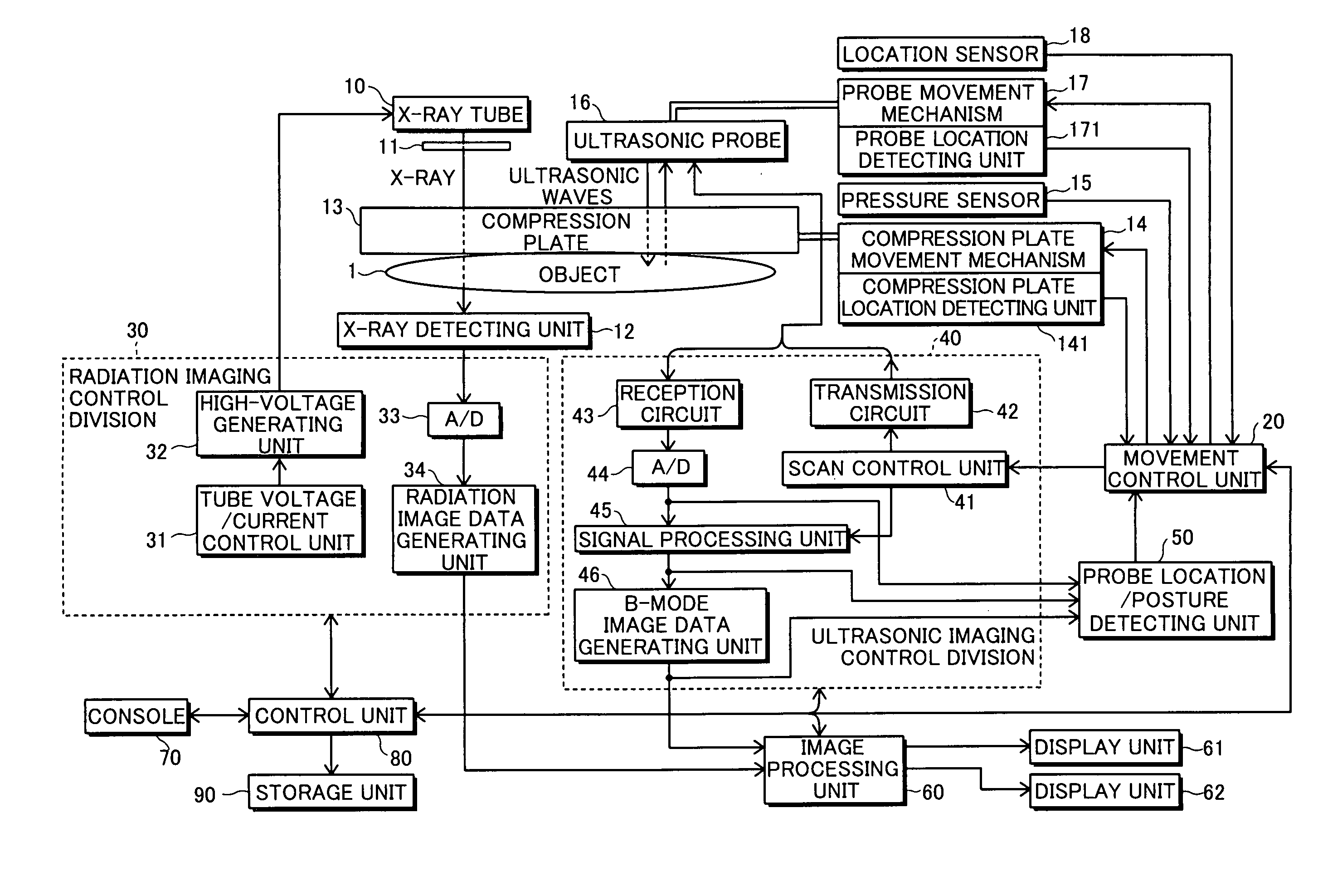
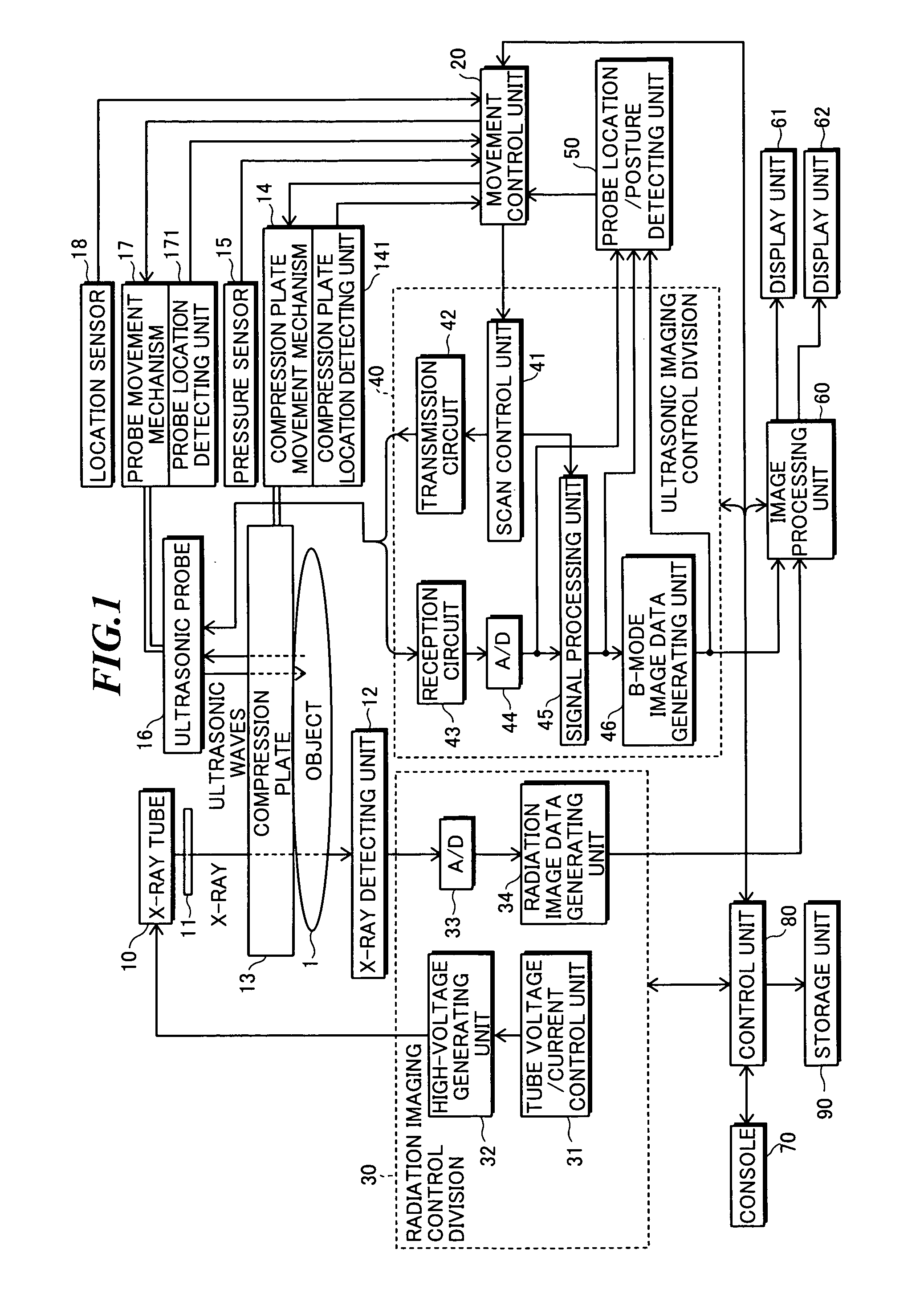
[0026]FIG. 1 is a block diagram showing a configuration of a medical imaging apparatus according to one embodiment of the present invention. The medical imaging apparatus has both a function of a radiation mammography apparatus for applying radiation to a breast and detecting the radiation transmitted through the breast to generate a radiation image, and a function of an ultrasonic diagnostic apparatus for transmitting ultrasonic waves to the breast and receiving ultrasonic echoes reflected within the breast to generate ultrasonic images. As below, the case of using an X-ray as radiation will be explained, however, α-ray, β-ray, γ-ray, electron ray, ultraviolet ray, or the like may be used.

[0027]As shown in FIG. 1, the medical imaging apparatus i...


PUM


Abstract

In a medical imaging apparatus for imaging mammary gland and breast while compressing the breast with a compression plate, the posture of an ultrasonic probe relative to the compression plate is kept constant and the moving motion of the ultrasonic probe is stabilized. The apparatus includes: an imaging stage; a compression plate; an ultrasonic probe provided to maintain acoustic connection to the compression plate, for transmitting ultrasonic waves according to drive signals and receiving ultrasonic echoes to output reception signals; an ultrasonic imaging unit for supplying the drive signals to the ultrasonic probe and generating image data based on the reception signals; a detecting unit for detecting a location and / or a posture of the ultrasonic probe relative to the compression plate; and a control unit for controlling the location and / or the posture of the ultrasonic probe based on a detection result of the detecting unit.

Description

CROSS-REFERENCE TO RELATED APPLICATION[0001]The present application claims priority from Japanese Patent Application No. 2008-198174 filed on Jul. 31, 2008, the contents of which are incorporated herein by reference in their entirety.BACKGROUND OF THE INVENTION[0002]1. Field of the Invention[0003]The present invention relates to a medical imaging apparatus for imaging mammary gland and breast while compressing the breast with a compression plate, for diagnoses of breast cancer or the like.[0004]2. Description of a Related Art[0005]Conventionally, an imaging method using radiation (X-ray, α-ray, β-ray, γ-ray, electron ray, ultraviolet ray, or the like) is utilized in various fields, and particularly, in the medical field, the imaging method is one of the most important means for diagnoses. Radiation images obtained by X-ray imaging (X-ray mammography) of breasts for breast cancer diagnoses are useful for finding calcification as a precursor of mass and cancer, but finding calcificati...

Claims


Application Information

Patent Timeline
Patent Type & Authority Applications(United States)
IPC IPC(8): A61B8/14
CPCA61B6/0414A61B6/502A61B6/4417A61B8/4254A61B8/4416A61B8/0825A61B8/4209
Inventor MIKAMI, YUJI
Owner FUJIFILM CORP
Why Eureka
Try Eureka