System and method for mechanically positioning intravascular implants

a technology of intravascular implants and mechanical positioning, which is applied in the field of therapeutic implant delivery and retrieval systems, can solve the problems of unfavorable operation, undesirable embolization downstream of the target site, and operator inability to operate, so as to avoid or minimize reduce the development of fatigue-related stresses, and facilitate the effect of avoiding fatigue-related stresses

Active Publication Date: 2010-02-04
TYCO HEALTHCARE GRP LP
View PDF111 Cites 148 Cited by
  • Summary
  • Abstract
  • Description
  • Claims
  • Application Information

AI Technical Summary

Benefits of technology

[0027]The positioner avoids or minimizes the development of fatigue-related stresses at the interface between the positioner and implant by permitting the unrestrained movement of the implant relative to the positioner, within the limitations defined by the implant interface. The development of implant interface stresses is minimized or avoided because the ball, rod, and implant are able to move in the axial and radial directions compared to the axis of the positioning system, to rotate about an axis of the rod or implant, and to move angularly so that implant is at an angle as compared to the axis of the positioning system.
[0028]The positioning system does not require an additional step of preparing a coil detachment mechanism because the positioner and implant are already in an engaged orientation when removed from packaging and prior to insertion into a patient. The positioner and implant thus provide a system that is ready for use out of the package. The positioning system also provides a direct connection between the actuation of a detachment mechanism and the detachment of the implant from the delivery system, without an intermediary process that must initiate and complete to achieve coil detachment. The positioning system thus achieves a fast preparatory and / or detachment time, which represents a short period of time between the opening of the packaging and the deployment of the implant. The positioning system can be prepared for use without delays relating to the preparation of the coil detachment mechanism, and can achieve detachment of the implant from the positioning system without delays resulting from an intermediate process that must be initiated and completed to achieve the detachment. The absence of such delays, and the connection of the detachment mechanism, provides a system that permits a fast and efficient deployment of implants at a target site. The reduction in the length of time required to prepare the positioning system advantageously increases the efficiency of the procedure because a coil detachment mechanism preparation step is not needed, thereby allowing the practitioner to attend to other duties during the invasive medical procedure. The reduced deployment time advantageously allows the length of the invasive medical procedure to be shortened because time is not needed for the detachment mechanism to achieve coil detachment. The short deployment time also allows the expended positioner to be removed soon after detachment and allow the next implant to be inserted and positioned in a given time interval.

Problems solved by technology

It is believed that there are numerous drawbacks and disadvantages to such electrolytic systems.
One disadvantage of this design is believed to be that the detachment segment must be positioned distally of microcatheter for release (i.e., the operator cannot “pre-release” the coil within microcatheter if desired).
Another disadvantage is believed to be that these systems require electrical insulation and isolation of the detachment segment to reduce the release of metallic particles created during detachment, which may cause unwanted embolization downstream of the target site.
Another disadvantage is believed to be that these systems require the practitioner to wait for an unknown amount of time, typically 10-180 seconds, until the implant coil is released, with the release monitored by feedback from a specialized system using complex electrical drivers.
Yet another disadvantage is believed to be that these systems generate “false positives” quite often, at a rate of 3-10%, that falsely indicate that the coil has been released when in fact it has not.
Further, as with any electrochemical reaction in solution, the system needs to be within ionic fluids to function, and it is believed that undesirable gases are formed at both the anode and the cathode.
Additionally, it is believed that there are guide wire and delivery system size limitations because these systems require a constant flow of electrolytes such as saline through the microcatheter to hasten the detachment time of the coil.
One disadvantage of this design is believed to be that such systems require complex catheter construction and rigorous purging to avoid the delivery of air emboli.
Even after purging, it is believed that some air emboli are usually left in the system and will be inevitably injected into the patient during the detachment process.
Another disadvantage is believed to be that these systems are time consuming to use because of the preparation of the pusher and because of the filling and attachment of pressure syringes.
These systems are believed to be less reliable than electrolytic systems and at times have either failed to release the coil or prematurely released the coil.
Additionally, with this type of design, it is believed that the delivery system is optimally sized for hydraulic detachment, and not sized to facilitate coil delivery or the action of the pusher-coil interface.
A disadvantage of this design is believed to be that the system will not work well in highly tortuous anatomy due to the diminishing torque transmission of the pusher, that is, the body of the pusher itself twists with little or no rotation of the threaded portion.
The unscrewing operation of the pusher is also believed to cause undesirable movement of the entire system that could cause misalignment with the target site and cause the coil to be positioned undesirously within the target vessel.
Also, the screw design is believed to require the operator to hyper-extend the pusher beyond the tip of the microcatheter to effect release and is non-retrievable at that point.

Method used


Image

  • System and method for mechanically positioning intravascular implants
  • System and method for mechanically positioning intravascular implants
  • System and method for mechanically positioning intravascular implants

Examples


Embodiment Construction

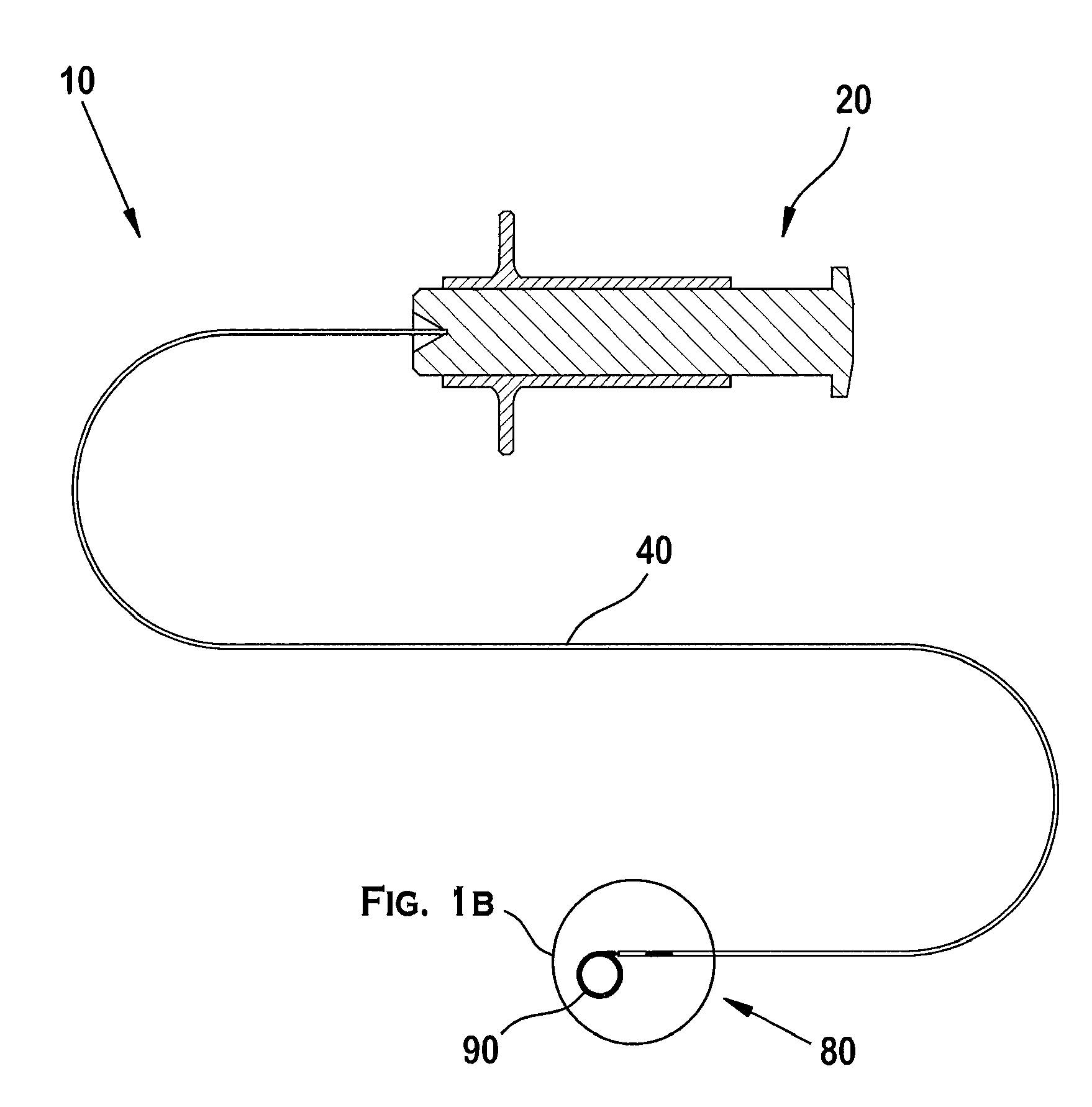
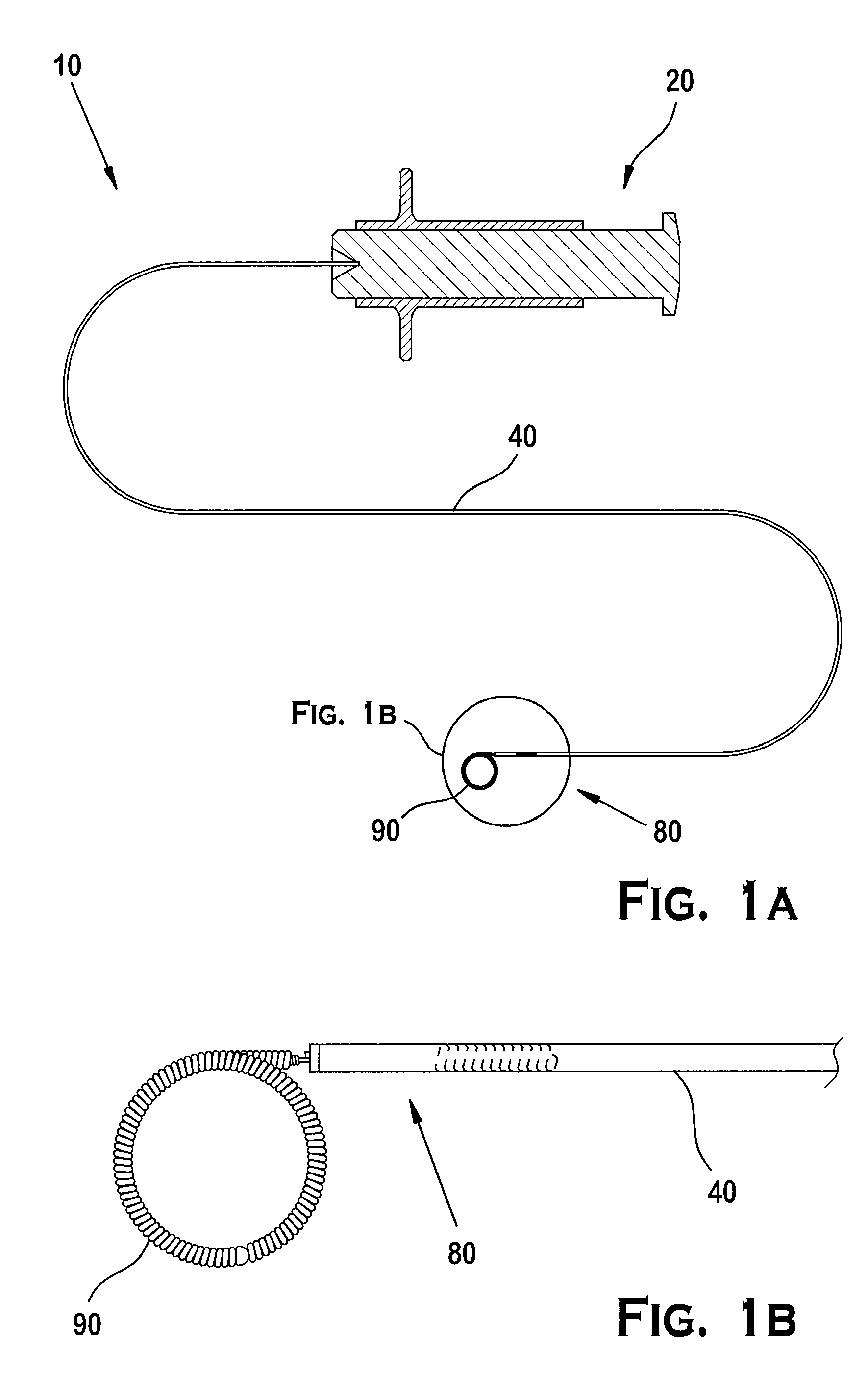
[0074]As illustrated in FIGS. 1A and 1B, the positioning system 10 preferably includes an actuator 20 operated by an operator, a positioner 40 engaging the actuator 20, and an implant interface 80 at the distal end of the positioner 40. A portion of the implant interface 80 engages a complementary portion of an implant 90.

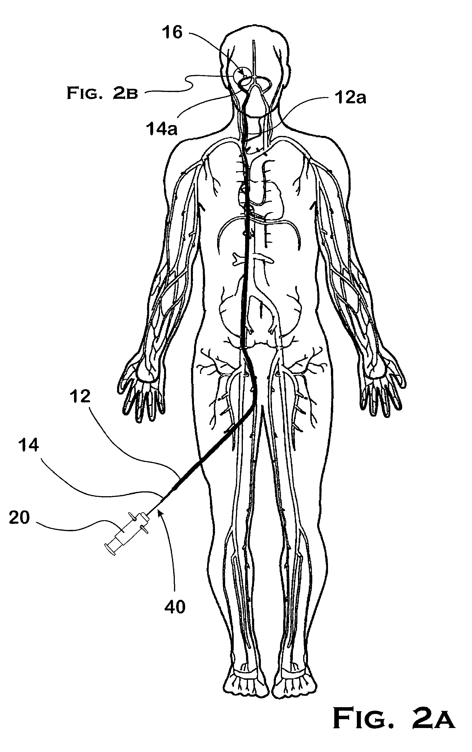
[0075]In the embodiment illustrated in FIGS. 1A and 1B, an operator uses a guide tube or guide catheter 12 to position a delivery tube or microcatheter 14 in a patient's vasculature, as illustrated in FIG. 2A. The procedure involves inserting the guide catheter 12 into the patient's vasculature through an access point such as the groin, and directing the distal end 12a of the guide catheter 12 through the vascular system until it reaches the carotid artery. After removing a guide wire (not shown) from the guide catheter 12, a microcatheter 14 is inserted into the guide catheter 12 and the distal end 14a of the microcatheter 14 subsequently exits the guide catheter ...


PUM


Abstract

An intravascular implant delivery system carries an implant by retaining an engagement member engaging the implant in a position proximal of an aperture at a distal end of the delivery system. The engagement member is retained proximal to the aperture by a cord that obstructs the movement of the engagement member through the aperture. The engagement member is free to rotate and move within an area defined by the delivery system, allowing the implant to react to forces imparted to the implant by the movement of the delivery system and implant through a delivery catheter. Once the implant is in a desired implant position, the cord is moved away from an aperture and the engagement member is allowed to move away from the delivery system.

Description

PRIORITY DATA AND INCORPORATION BY REFERENCE[0001]This application claims benefit of priority to U.S. Provisional Patent Application Nos. 60 / 792,414, filed Apr. 17, 2006, and 60 / 894,589, filed Mar. 13, 2007, which are incorporated by reference in their entireties.TECHNICAL FIELD[0002]This invention relates to therapeutic implant delivery and retrieval systems and, more particularly, to a system with a member that mechanically engages an implant to be positioned in a body. The positioning includes delivering and deploying an implant at a target site, or removing an implant from the target site. The invention also relates to implants and, more particularly, to implants adapted to be mechanically retained by a delivery and retrieval system.BACKGROUND ART[0003]Sometimes a body cavity, such as an aneurysm, is located in a surgically remote, delicate, and torturously formed region, such as within the cerebral vasculature, that requires a specialized delivery system to navigate to the regi...

Claims


Application Information

Patent Timeline
Patent Type & Authority Applications(United States)
IPC IPC(8): A61B17/00A61F2/82
CPCA61B17/12022A61B17/12113A61B17/1214A61B17/12154A61B17/12172A61B19/54A61B2017/12054A61B2017/2924A61F2/01A61F2/82A61F2230/0006A61B17/12145A61B2017/1205A61B2017/2913A61B90/39A61M25/00A61M31/00A61M37/00
Inventor STRAUSS, BRIAN MICHAELSLEE, EARL HOWARDCARRILLO, RAMON TORRESVU, KHOA DANGPATTERSON, WILLIAM ROBERTLIANG, JESSICABEIN, RICHARD STEPHENHEWITT, TODD JEFFREYFAUGHT, STACY LEONDIVINO, VINCEDRYSEN, DARRELL CHRISTOPHERASHBY, MARK PHILIPKLOTZ, JUSTIN ARTHURSANSON, MARIA DE JESUSBRENNAN, SCOTT WILLIAMWILBUR, LAWRASON CHARLESOESTREICH, LESTER EUGENE
Owner TYCO HEALTHCARE GRP LP
Why Eureka
Try Eureka