System and method for braking system control in distributed power vehicles

Active Publication Date: 2010-02-04
GE GLOBAL SOURCING LLC
View PDF36 Cites 9 Cited by
  • Summary
  • Abstract
  • Description
  • Claims
  • Application Information

AI Technical Summary

Benefits of technology

[0008]In this manner, in one aspect, an independent secondary signal is provided from the brake system to the distributed power control system for conveying the level of a penalty brake application, such that the actual level of the penalty brake application implemente

Problems solved by technology

However, if the first communication link fails (meaning it cannot convey the information), the brake system redundantly transmits the info

Method used


Image

  • System and method for braking system control in distributed power vehicles
  • System and method for braking system control in distributed power vehicles
  • System and method for braking system control in distributed power vehicles

Examples


Embodiment Construction

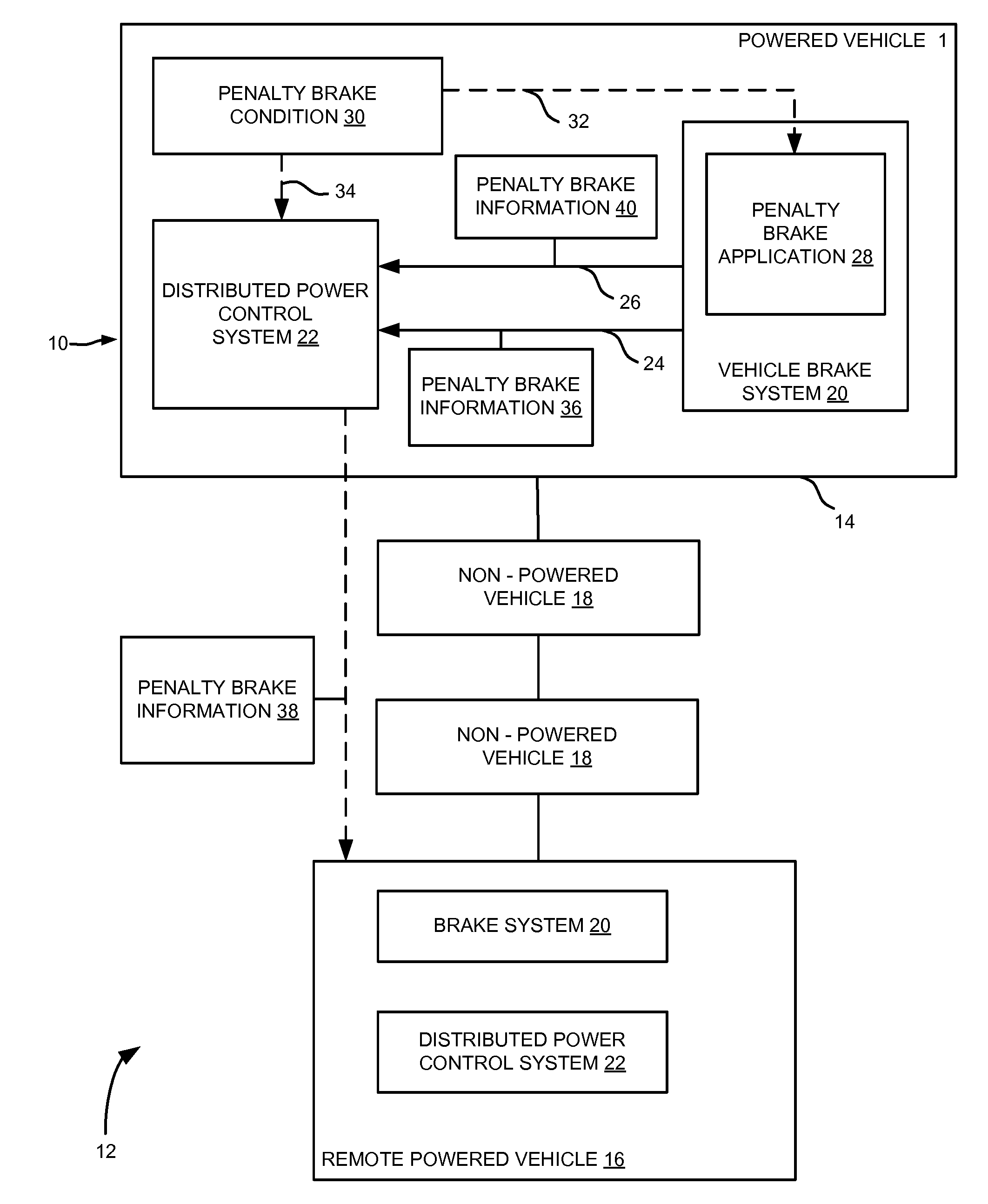
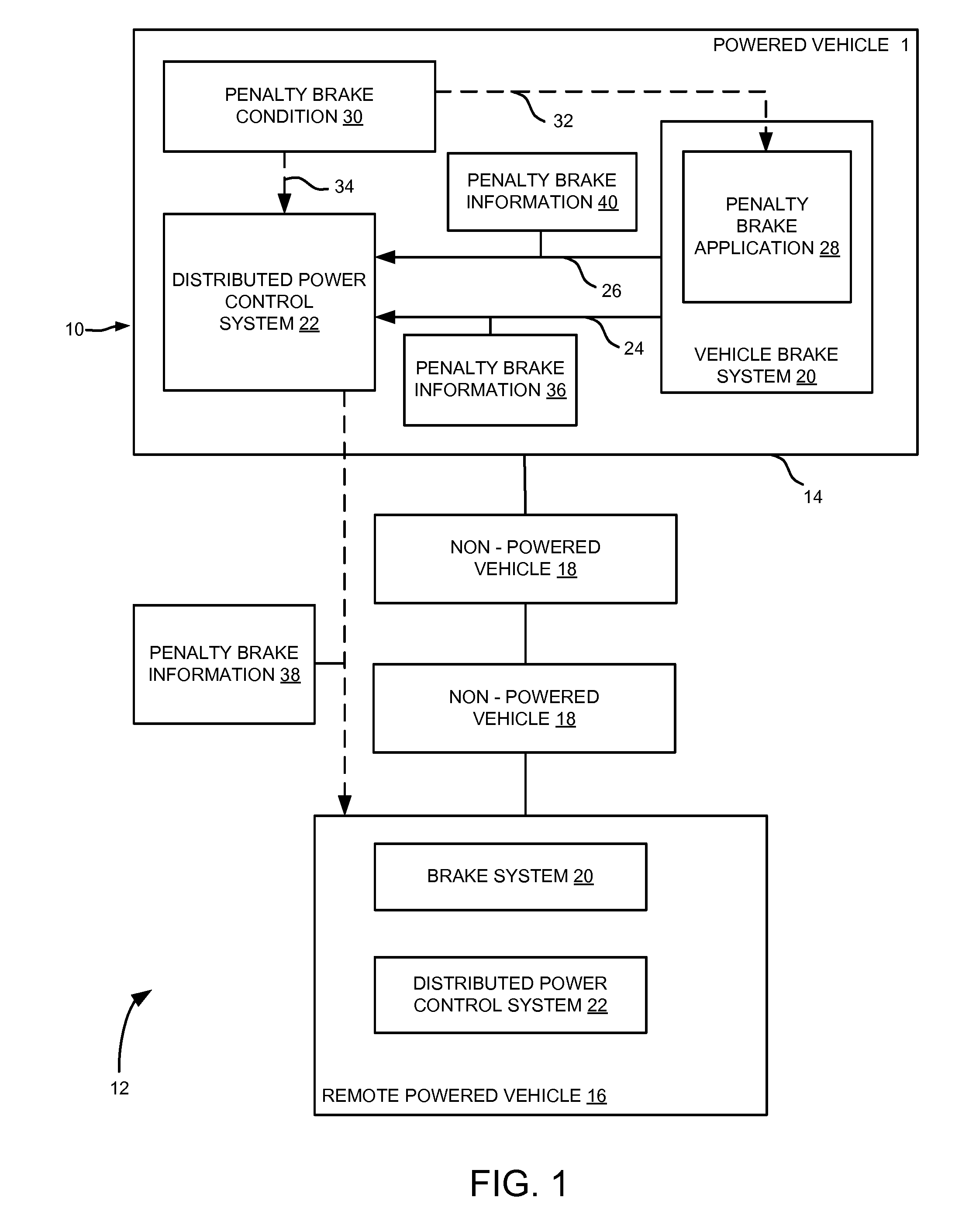
[0015]Turning first to FIG. 1, an embodiment of the present invention relates to a brake control system 10 for a distributed power vehicle system 12. (As noted above, “distributed power vehicle system” refers to two or more powered vehicles 14, 16 that are linked together and controlled in concert to move themselves and possibly pull or otherwise move one or more non-powered load vehicles 18.) The brake control system 10 includes a vehicle brake system 20 and a distributed power control system 22 in a first vehicle of the distributed power vehicle system 12, e.g., in a first powered vehicle 14. (Here, “first” refers not necessarily to a lead vehicle, but is instead an arbitrary designation for distinguishing the first vehicle 14 from other vehicles 16, it being recognized that the functionality of the present invention need not necessarily be embodied solely in a lead vehicle.) The system 10 also includes first and second separate communication links 24, 26 between the brake system ...


PUM


Abstract

A brake control system for a distributed power vehicle system includes a brake system and a distributed power control system in a first vehicle, and first and second separate communication links between the brake system and the distributed power control system. In operation, upon the initiation of a penalty brake application, the brake system transmits information about the brake level of the penalty brake application to the distributed power control system, over at least the first communication link. However, if the first communication link fails, the brake system redundantly transmits the information about the level of the penalty brake application to the distributed power control system over the second communication link. The information is transmitted from the distributed power control system in the first vehicle to remote vehicles for carrying out the penalty brake application.

Description

[0001]This application claims the benefit of U.S. Provisional Application Ser. No. 61 / 085,578, filed Aug. 1, 2008, incorporated by reference herein in its entirety.FIELD[0002]The subject matter of certain embodiments of the present invention relates to vehicles and, more particularly, to braking system applications or controls in distributed power vehicles.BACKGROUND[0003]In distributed power vehicle systems, two or more powered vehicles are linked together and controlled in concert to pull or otherwise move one or more non-powered load vehicles. For example, in the case of a distributed power-based train, there is typically a lead locomotive followed by a number of load railcars for hauling freight, passengers, or the like, with one or more remote locomotives distributed throughout the train for helping with moving and braking the load railcars. In operation, when a throttle setting is established in the lead locomotive (e.g., by a train operator selecting a desired notch level), a...

Claims


Application Information

Patent Timeline
IPC IPC(8): G05D1/00
CPCB60T17/18B60T7/18B60T7/12
Inventor SMITH, EUGENE A.WHEELER, MARK WAYNECORRY, JAMES GLENPALANTI, ROBERTRATNESAR, RABI
Owner GE GLOBAL SOURCING LLC
Why Eureka
Try Eureka