Position detecting apparatus and method used in navigation system

a technology of positioning detection and navigation system, which is applied in surveying, navigation, instruments, etc., can solve the problems of insufficient long-time use of navigation, mounting error, mounting error, etc., and achieve the effect of improving the accuracy of vehicle position calculation, and increasing the accuracy of moving distance vector

Active Publication Date: 2010-02-04
ALPINE ELECTRONICS INC
View PDF12 Cites 40 Cited by
  • Summary
  • Abstract
  • Description
  • Claims
  • Application Information

AI Technical Summary

Benefits of technology

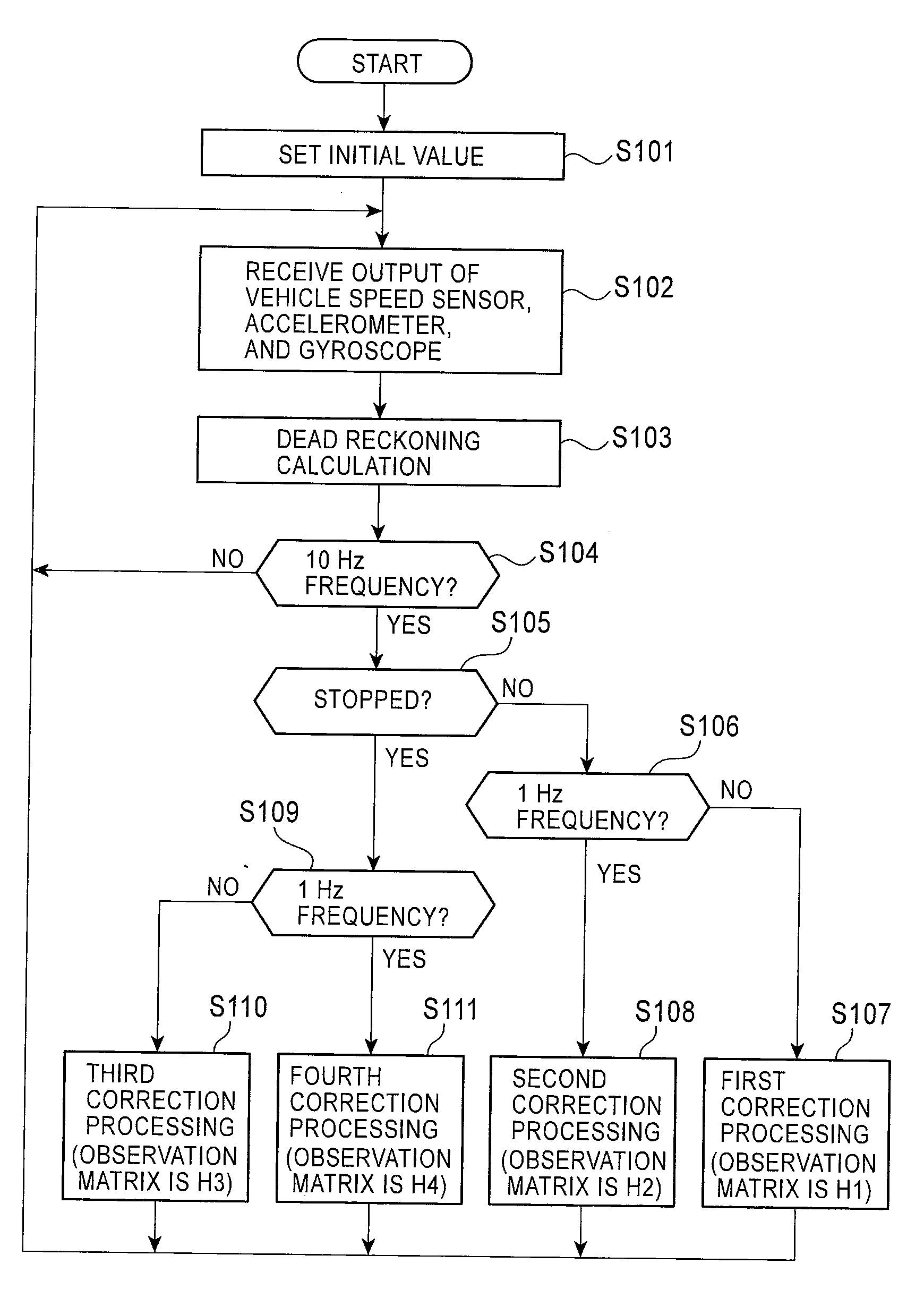
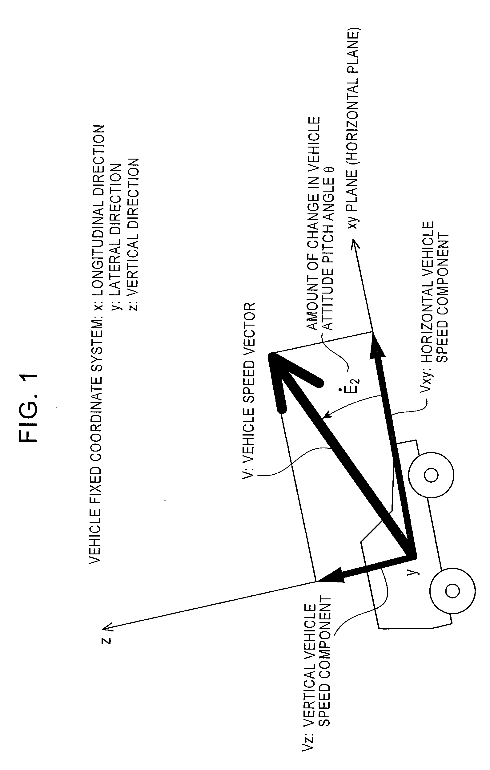
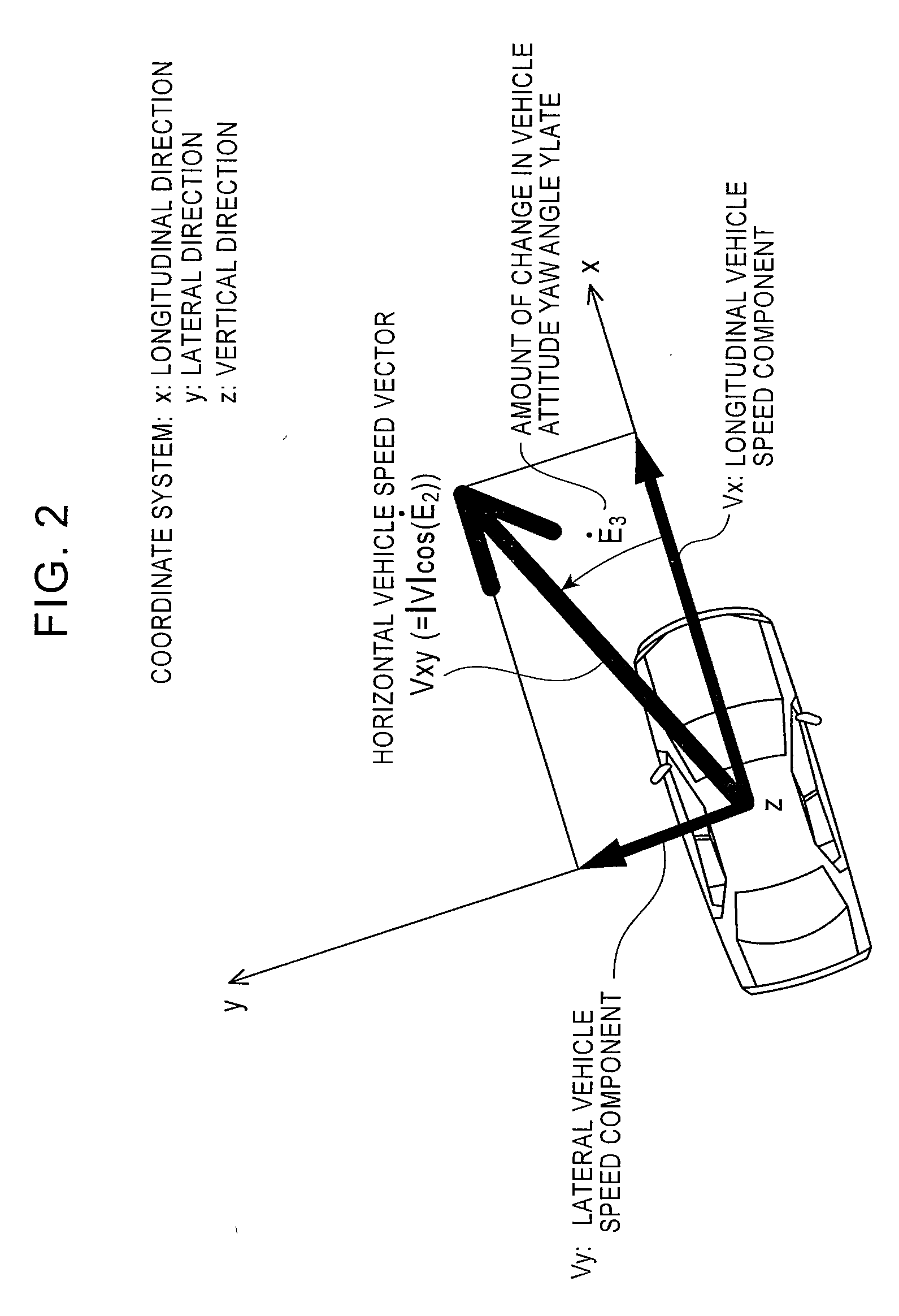
[0052]According to the present embodiment, if a vehicle attitude angle, for example, a pitch angle or a yaw angle is changed during driving, a vehicle moving distance is resolved into a vehicle longitudinal component, a vehicle lateral component, and a vehicle vertical component in consideration of amounts of change in pitch angle and yaw angle, whereby an accuracy of a moving distance vector can be increased, and an accuracy of calculation for a vehicle position can be improved.
[0053]Further, if a vehicle attitude angle, for example, a pitch angle or a yaw angle is changed during driving, a vehicle moving distance is resolved into a vehicle longitudinal component Vxb-obs, a vehicle lateral component Vyb-obs, and a vehicle vertical component Vzb-obs in consideration of amounts of change in pitch angle and yaw angle, whereby an accuracy of a moving distance vector can be increased, and an accuracy of a speed, a sensor attitude angle, and a sensor mounting angle can be improved.
[0054]Further, a positional accuracy and a bearing accuracy can be improved with a system configuration having fewer sensors. Hence, the cost of the navigation system can be reduced.
[0055]Moreover, a relative height accuracy can be improved and thus, the present invention is applicable to a determination unit for indicating a junction between an expressway and an open road under the expressway.

Problems solved by technology

However, noise or other such error included in the sensor output increases over time at each integral calculation and thus, navigation is inadequate for long-time use.
However, as shown in FIG. 19A, a mounting error is involved when mounted.
However, a mounting error is involved when mounted.
This system includes many sensors and thus is costly.
However, the system having fewer sensors involves a problem of lower accuracy. FIG. 22 is an explanatory view of a correspondence relationship between sensor configuration and accuracy. FIG. 22 shows (1) a bearing error (deg) between a road bearing and an estimated vehicle bearing in the case where a vehicle is stopped in parallel to the road at the top floor of a 10-story spiral parking out of GPS range and (2) a difference in estimated height (m) in the case where a vehicle enters the parking from a ground-floor entrance and drives up to the top floor and then returns to a ground-floor exit.

Method used


Image

  • Position detecting apparatus and method used in navigation system
  • Position detecting apparatus and method used in navigation system
  • Position detecting apparatus and method used in navigation system

Examples


Embodiment Construction

(A) Principle of the Present Invention

(a) Analysis of Problems in the Related Art

[0078]A dead reckoning calculating unit 12 in FIG. 15 calculates a state quantity inclusive of each axial velocity, each axial position, and a sensor attitude based on a dead reckoning calculating algorithm. According to the dead reckoning calculating algorithm of the related art, a position Pn in an NED coordinate system is derived from the following position equation:

[Expression 11]

pn(k+1)=pn(k)+Tnbsb  (11)

[0079]In Expression 11, the following conditions are satisfied.

[Expression12]pn=[NED]=[NorthwarddistanceEastwarddistanceDownwarddistance](12a)sb=[NpL00](12b)

[0080]where Tnb represents a transform matrix for transforming from a vehicle fixed coordinate system to the NED coordinate system. Expression 12a shows a position vector, and Expression 12b shows a vehicle moving distance vector in the vehicle fixed coordinate system. In Expression 12b, Np represents the number of pulses per sample time, and L ...


PUM


Abstract

A position detecting apparatus and method used in a navigation system, which can improve positional accuracy and bearing accuracy even in a system equipped with few sensors, are provided. A position detecting apparatus used in a navigation system for detecting a vehicle position includes: a sensor unit including a vehicle speed sensor, an acceleration sensor, and an angular velocity sensor; and a dead reckoning calculating unit for calculating state quantity inclusive of a current vehicle position, a vehicle speed, and a vehicle attitude angle based on a signal output from each of the sensors at a predetermined periodic interval. The dead reckoning calculating unit includes: a movement calculating unit for calculating a movement during a period from a previous state quantity calculation time up to a current state quantity calculation time; a change amount detecting unit for calculating an amount of change in vehicle attitude; a movement resolving unit for resolving the movement into a vehicle longitudinal component, a vehicle lateral component, and a vehicle vertical component based on the amount of change in vehicle attitude; and a state quantity calculating unit for determining, by calculation, a vehicle position at the current state quantity calculation time using each of the components.

Description

RELATED APPLICATIONS[0001]The present application claims priority to Japanese Patent Application Number 2008-195577, filed Jul. 30, 2008, the entirety of which is hereby incorporated by reference.BACKGROUND[0002]1. Field of the Invention[0003]The present invention relates to a position detecting apparatus and method used in a navigation system, and more specifically to a position detecting apparatus and method used in a navigation system which correct a state quantity measured with a dead reckoning navigation unit (a state quantity including a vehicle position, a vehicle speed, and an attitude of a sensor or a vehicle) at a predetermined periodic interval and then recalculate a state quantity based on the corrected state quantity and output the calculated state quantity with the dead reckoning navigation unit.[0004]2. Description of the Related Art[0005]Dead reckoning navigation systems are configured using a vehicle speed pulse sensor as a vehicle distance sensor and an inertial se...

Claims


Application Information

Patent Timeline
Patent Type & Authority Applications(United States)
IPC IPC(8): G01C21/12
CPCG01C21/26G01C21/12
Inventor WATANABE, TAKAYUKISAKAGAMI, TAKEHIKOWAKAMATSU, KOTARO
Owner ALPINE ELECTRONICS INC
Why Eureka
Try Eureka