Steam turbine closed loop geo-thermal cooling

a closed-loop geothermal cooling and steam turbine technology, applied in the direction of domestic cooling equipment, lighting and heating equipment, electric generator control, etc., can solve the problems of unsuitable water from many of these aquifers for consumption or irrigation, and achieve the effect of reducing the amount of water and reducing the amount of potential pollution of water systems

Inactive Publication Date: 2010-02-11
HORIZON ENERGY ASSOCS
View PDF12 Cites 15 Cited by
  • Summary
  • Abstract
  • Description
  • Claims
  • Application Information

AI Technical Summary

Benefits of technology

[0035]7. a new and useful system and method for minimizing the amount of water employed reducing the amount of potential pollution of water systems.

Problems solved by technology

Water from many of these aquifers is unsuitable for consumption or irrigation and could be used as for heat transfer to the rock encasing the aquifer.

Method used


Image

  • Steam turbine closed loop geo-thermal cooling
  • Steam turbine closed loop geo-thermal cooling
  • Steam turbine closed loop geo-thermal cooling

Examples


Embodiment Construction

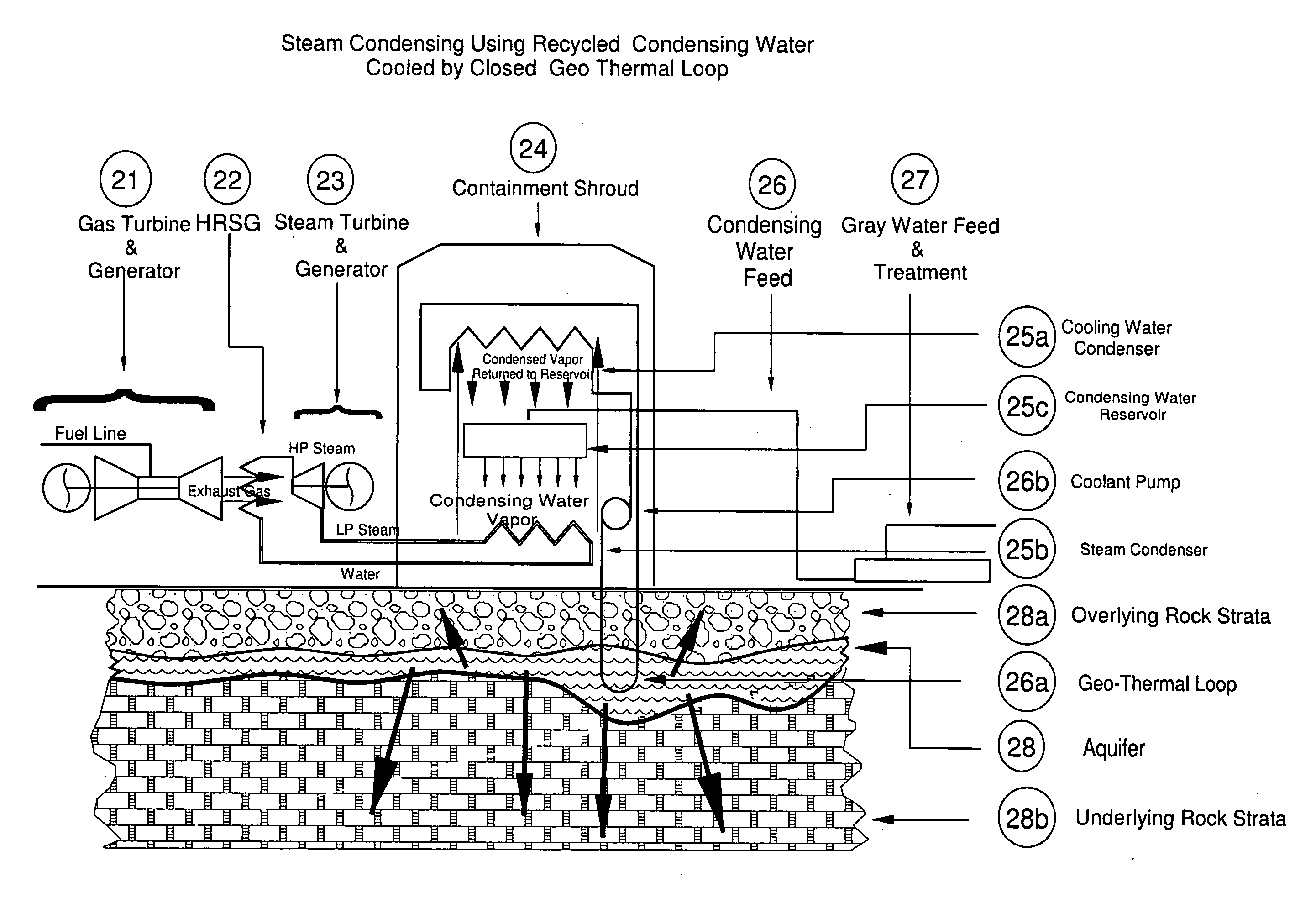
[0052]In FIG. 2 there is shown a containment shroud 24 erected over the steam condenser 25b. In some cases, a cooling tower could be converted to serve as the containment shroud. In other cases, a simple structure similar to a storage tank would serve to contain the vapor within the containment shroud. The condensing water vapor elevates through another heat exchanger the cooling water condenser 25a where it is cooled by a cooling fluid flowing through the geo-thermal loop 26a, thereby condensing the condensing water vapor to liquid, where it is recovered and returned to a cooling water reservoir 25c for reuse, together with a feed of condensing water at 26, as and when necessary.

[0053]As required, additional condensing water is added to the condensing water reservoir 25c from the condensing water feed 26 although in much smaller quantities than with conventional re-circulating technology. Although it is shown that the primary source of condensing water will be from a gray water sou...


PUM


Abstract

A power generation system for generating electricity using a steam turbine engine that yields high-pressure steam has been developed using a preferably non-toxic coolant circulating in a closed loop that passes through a rock and earth aquifer, for directly and/or indirectly condensing the low-pressure steam from the low-pressure side of the steam turbine into a liquid phase for re-circulation to the steam turbine, whereby the coolant acts to dissipate the heat from the low-pressure steam through the aquifer to the rock and earth encasing the aquifer. In one embodiment a containment shroud is employed to recycle condensing water utilized to condense the condensing vapor emitted from a steam condenser. In a second embodiment a sealed steam condenser is utilized through which the low-pressure steam passes, and water (or other suitable fluid) from an enclosed condensing water reservoir, through which the coolant is circulated, is employed to condense the low-pressure steam in the steam condenser. In yet another embodiment, the coolant is introduced directly into the steam condenser. In a further embodiment an intermediate refrigeration system pump is employed together with the coolant, for condensing the low-pressure steam.

Description

RELATED APPLICATIONS[0001]Applicant claims priority with respect to the instant application to U.S. Provisional Patent Application No. 61 / 086,845 filed Aug. 8, 2008, and U.S. Provisional Application No. 61 / 148,808 filed Jan. 30, 2009. Each of the aforementioned priority applications is hereby incorporated herein by reference in their entirety.BACKGROUND OF THE INVENTION[0002]1. Field of the Invention[0003]The present invention relates to the field of steam turbines, and, in particular, employing preferably a non-toxic coolant that is circulated through a closed loop system passing through a rock and earth aquifer for condensing low-pressure steam from the low-pressure side of a steam turbine employed for generating electricity.[0004]2. The Prior Art / The Issues[0005]Conventional commercial electrical power generation is often achieved using a heat engine such as a steam turbine in which high-pressure steam is expanded in a turbine driving a generator to produce electricity. Frequentl...

Claims


Application Information

Patent Timeline
Patent Type & Authority Applications(United States)
IPC IPC(8): F01K13/00F01K11/00F25D23/12
CPCF01K9/003Y02E20/16F01K23/10
Inventor BROWN, JEFFREY J.
Owner HORIZON ENERGY ASSOCS
Why Eureka
Try Eureka