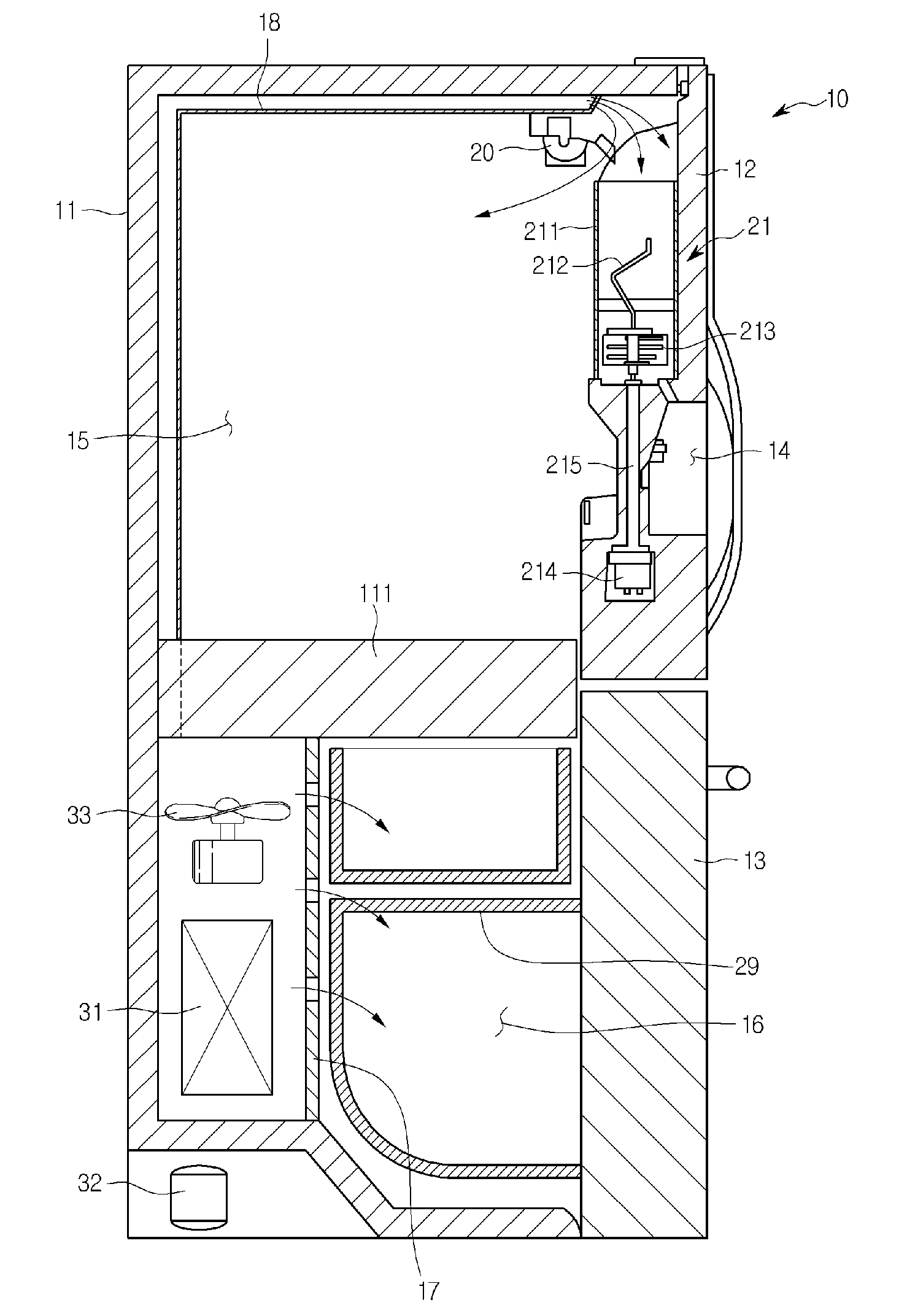
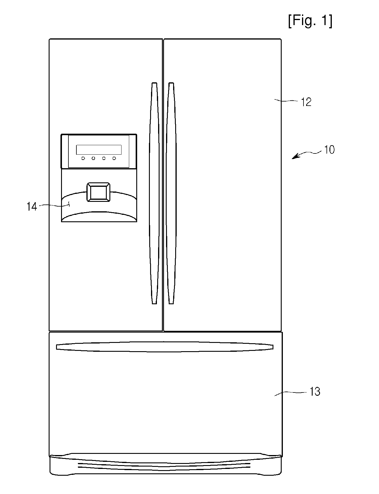
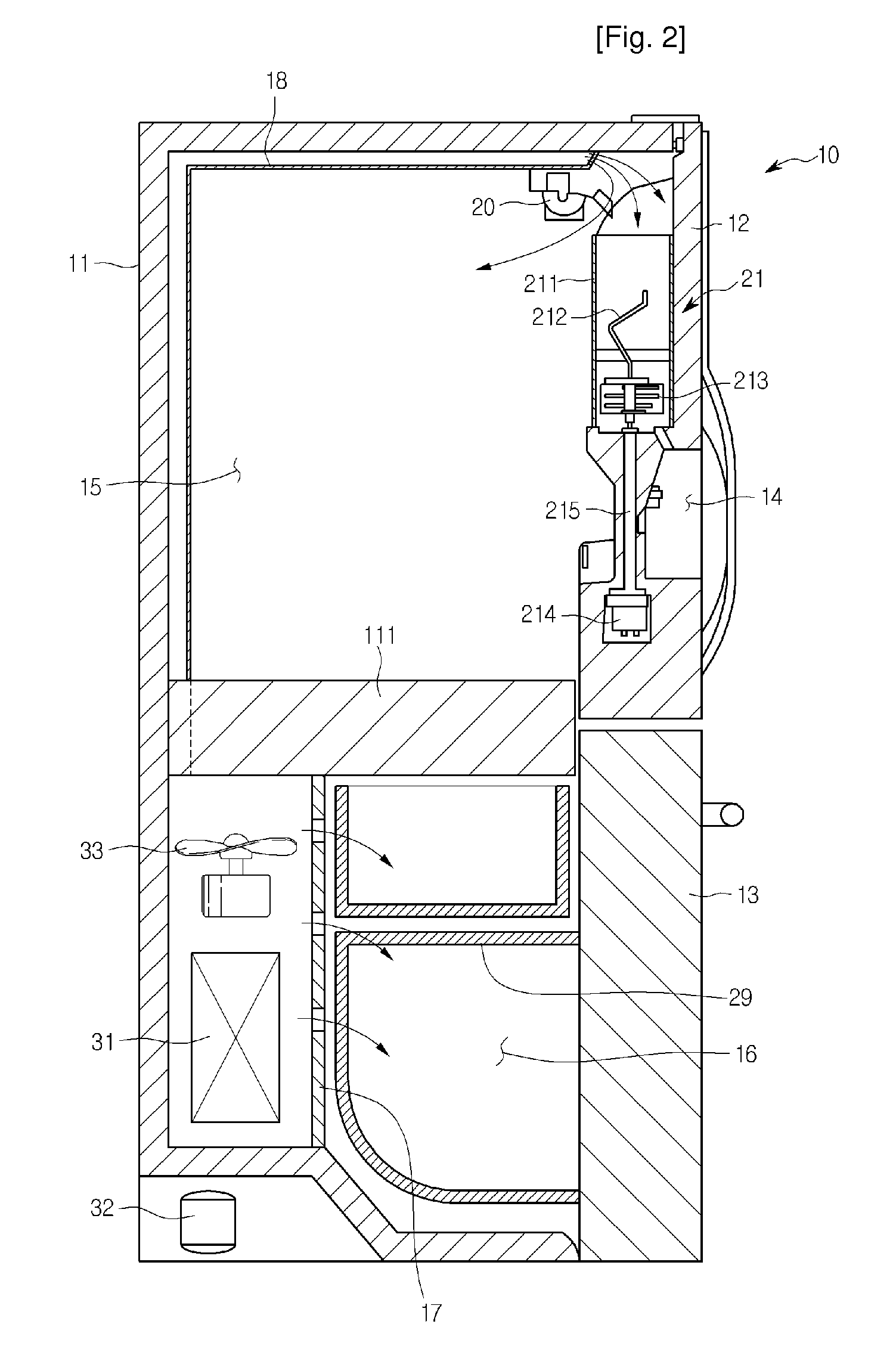
Ice making system and method for ice making of refrigerator

a technology of refrigerator and ice making system, which is applied in the field of ice making system and ice making method of refrigerator, can solve the problems of difficult ice formation with refrigerant supplied for use in the refrigeration compartment, ice cannot be completely formed, and formed ice will melt quickly, so as to reduce the manufacturing cost of the refrigerator and simplify the manufacturing process. , the effect of saving energy

Inactive Publication Date: 2010-02-11
LG ELECTRONICS INC
View PDF7 Cites 51 Cited by
  • Summary
  • Abstract
  • Description
  • Claims
  • Application Information

AI Technical Summary

Benefits of technology

[0015]As described above, in an ice making system and ice making method for a refrigerator according to the present disclosure, because a separate duct for supplying cold air to the ice maker does not need to be formed, the manufacturing process of the refrigerator is simplified and the manufacturing cost of the refrigerator is also reduced.
[0016]Also, because a portion of refrigerant used in a freezing cycle of the refrigerator is used for ice making, additional energy is not required for ice making, thus providing an energy saving benefit.
[0017]In addition, even with the ice maker provided in the refrigeration

Problems solved by technology

When an ice maker and ice bank are provided in the refrigeration compartment, because the inside of the refrigeration compartment is maintained at temperatures above freezing, it is difficult to form ice with refrig

Method used


Image

  • Ice making system and method for ice making of refrigerator
  • Ice making system and method for ice making of refrigerator
  • Ice making system and method for ice making of refrigerator

Examples


first embodiment

[0051]FIG. 3 is a perspective view showing a schematic structure of an ice maker according to the present disclosure.

[0052]Referring to FIG. 3, an ice maker 20 according to a first embodiment of the present disclosure includes a tray 201 that stores water used for making ice, a freezing pipe 40 extending into the tray 201, and a water supplying device for supplying water to the tray 201.

[0053]Specifically, the water supplying device includes a water tank 42 storing water, a pump 41 that pumps water within the water tank 42, and a water supplying pipe 43 extending from the pump 41 to the tray 201. Also, a dispenser connecting pipe 44 may branch off from a side of the water supplying pipe 43, and a redirecting valve 45 may be installed at the branching point to selectively control the flow direction of water. In more detail, the dispenser connecting pipe 44 extends toward the dispenser to dispense drinking water to users.

[0054]A pivoting axis 202 extends at either side of the tray 201...

second embodiment

[0081]FIG. 9 is a perspective view showing a schematic structure of an ice maker according to the present disclosure.

[0082]Referring to FIG. 9, an ice maker according to a second embodiment of the present disclosure is the same as that in the first embodiment, except for having a heater 50 for ice separation attached along the outer surface of the freezing pipe 40 instead of the separate freezing pipe and the return pipe structure for ice separation. Thus, descriptions of elements that are the same as in the first embodiment will be omitted hereafter.

[0083]To briefly describe an ice making process with the above structure, low temperature refrigerant flows to the freezing pipe 40, and water within the tray 201 freezes on the surfaces of the protruding portions 401.

[0084]At a predetermined point, either the tray 201 is rotated to remove residual water, or a draining pump operates to remove the residual water. The method for removing residual water has already been described in the fi...


PUM


Abstract

The present disclosure provides a refrigerant pipe, through which low temperature and low pressure refrigerant flows, directly on a tray, allowing for quick ice formation even when an ice maker is installed in a refrigeration compartment, and allowing for transparent chunks of ice to be made.

Description

TECHNICAL FIELD[0001]The present disclosure relates to an ice making system and an ice making method of a refrigerator.BACKGROUND ART[0002]In general, a refrigerator is a home appliance that stores food at low temperatures to keep the food fresh for a prolonged period.[0003]Specifically, a refrigerator provides a refrigeration compartment that maintains an inside temperature within a range of 1-4° C. to preserve foods such as vegetables in a fresh state, and a freezer compartment that maintains an inside temperature of around −18° C. to preserve foods such as meat and fish in a frozen state.[0004]Refrigerators may be divided according type into top mount refrigerators with the freezer compartment above the refrigeration compartment, bottom freezer refrigerators with the freezer compartment below the refrigeration compartment, and side by side refrigerators with the freezer and refrigeration compartments provided beside one another.[0005]Refrigerators can also be divided into french ...

Claims


Application Information

Patent Timeline
IPC IPC(8): F25C5/08F25B1/00F25C1/00F25D17/04
CPCF25C1/08F25D2400/06F25C1/225F25C1/24F25C5/046F25C5/08F25C5/10F25C2305/022F25C2400/10F25C2400/14F25C2500/08F25C2700/04F25D17/065F25D23/028F25D23/04F25D23/126F25C1/10F25C5/185F25D2317/062F25C1/25F25C2305/0221
Inventor KIM, JU-HYUNSHIN, JONG-MIN
Owner LG ELECTRONICS INC
Why Eureka
Try Eureka