Fail-safe power control apparatus

a power control apparatus and failure-safe technology, applied in the direction of fault response, instruments, electric digital data processing, etc., can solve the problems of increasing the speed of transporting equipment to a dangerous level, reducing the number of safety devices, etc., and achieve the effect of saving the calculation capacity of the controller and faster calculation of the envelope curv

a power control apparatus and failure-safe technology, applied in the direction of fault response, instruments, electric digital data processing, etc., can solve the problems of increasing the speed of transporting equipment to a dangerous level, reducing the number of safety devices, etc., and achieve the effect of saving the calculation capacity of the controller and faster calculation of the envelope curv

US20100032246A1Active Publication Date: 2010-02-11KONE CORP

Image

  • Fail-safe power control apparatus
  • Fail-safe power control apparatus
  • Fail-safe power control apparatus

Examples


Embodiment Construction

[0068]The following example is a description of an elevator system provided with a fail-safe power control apparatus.

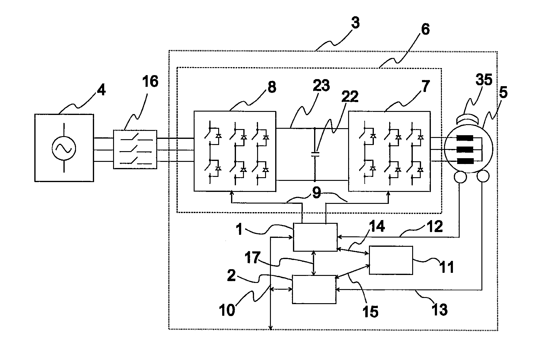
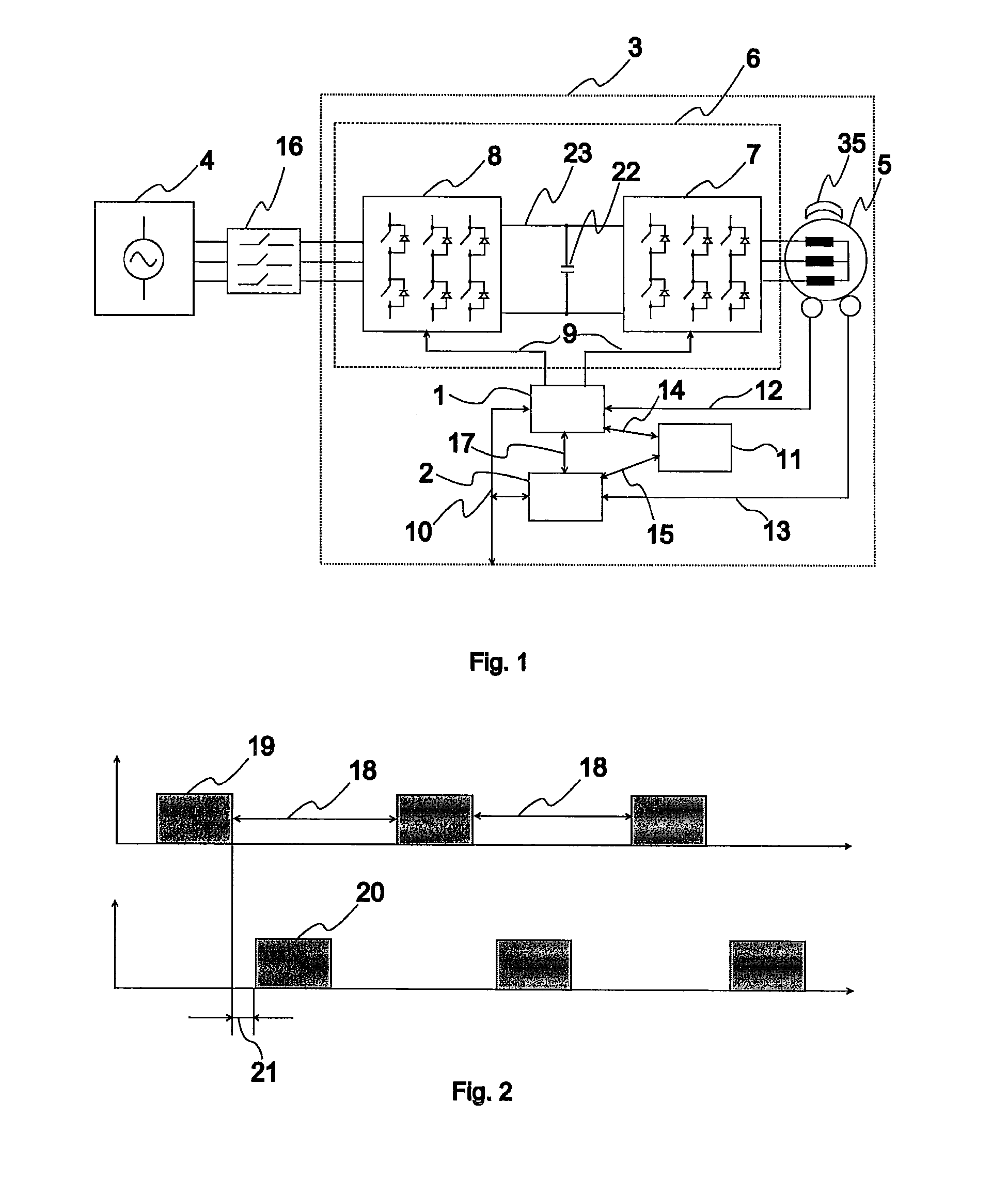
[0069]FIG. 1 represents a fail-safe power control apparatus according to the invention. The power supply circuit 6 comprises a mains converter 8 and an inverter 7. The mains converter converts a sinusoidal mains voltage 4 into a direct voltage, which is passed to the direct-voltage intermediate circuit 23 of the power supply circuit. The direct-voltage intermediate circuit comprises an energy storage 22 for smoothing the voltage. The inverter 7 converts the direct voltage into a variable-frequency and variable-amplitude voltage for feeding a motor 5. The mains supply is additionally provided with a main switch 16.

[0070]A second controller 2 measures the motor speed 13 and adjusts the measured speed according to a speed reference 59 as far as possible by transmitting via a communication bus 17 a motor-torque set value corresponding to the difference between the speed r...


PUM


Abstract

The invention relates to a fail-safe power control apparatus (3) for supplying power between an energy source (4) and the motor (5) of a transport system. The power control apparatus comprises a power supply circuit (6), which comprises at least one converter (7, 8) containing controllable change-over switches (32), and the power control apparatus comprises means (24) for controlling the converter change-over switches, a data transfer bus (10), at least two controllers (1, 2) adapted to communicate with each other, and a control arrangement (11) for controlling a first braking device, and possibly a control arrangement (43) for controlling a second braking device.

Description

FIELD OF THE INVENTION [0001]The present invention relates to a fail-safe power control apparatus as defined in the preamble of claim 1.PRIOR ART [0002]Transport systems, such as elevator systems, are traditionally provided with a separate control system for controlling the transport system and a separate safety system for ensuring the safety of the transport system.[0003]The control system of an elevator system comprises at least an elevator motor, an elevator controller and a power control apparatus for supplying power to the elevator motor. The elevator controller comprises an elevator group control function and functions for the handling of car calls and landing calls.[0004]The safety system of an elevator system comprises a safety circuit, which comprises a series circuit of one or more safety contacts that open in a failure situation, and safety devices activated upon opening of the safety circuit, such as a machine brake or a car brake. Moreover, the safety system may compris...

Claims


Application Information

Patent Timeline
11 Feb 2010
Publication
US20100032246A1
IPC
B66B5/04
CPC
B66B1/30; B66B1/343; B66B1/308; B66B5/02
Inventors
KATTAINEN, ARI; KALLIONIEMI, ANTTI