Ballast water treating apparatus

a technology of ballast water and treating apparatus, which is applied in the nature of treatment water, waterborne vessels, chemical/physical processes, etc., can solve the problems of inability to sterilize cholera, difficult to implement, and adversely affect the ecological system in the area

Inactive Publication Date: 2010-02-11
OHR LAB CORP +1
View PDF9 Cites 17 Cited by
  • Summary
  • Abstract
  • Description
  • Claims
  • Application Information

AI Technical Summary

Benefits of technology

[0015]According to these experiments, the in-line mixer is effective at sterilizing ballast water because it can destroy the cell membranes of planktons by the combined effect of three actions, i.e., (1) pressurization by the swirling flow that presses the ballast water against the inside surface of a pipe, (2) collisions achieved by causing the swirling flow of the ballast water to crash against a multiplicity of projections that are formed on the inside surface of a pipe, and (3) shock waves due to cavitation. Such shock waves are generated as follows. A cavity generated at a center of the swirling flow of the ballast water is under low pressure; therefore, bubbles form, and when the bubbles grow to sufficient size they burst due to the higher pressure of the ballast water surrounding the cavity. This dynamical action is effective for sterilizing planktons and larva of tens to hundreds of microns in size. To better assure the desired effect, an in-line mixer that can cause a faster swirling flow is sought.
[0041]In the in-line mixer of claim 2 of the present invention, the through-hole of the vane seat is in effect an extension from the subsidiary tubular part, which means that the blades arranged in the through-hole are arranged at the subsidiary tubular part. Accordingly, the flow rate of the ballast water is accelerated and is fast, so that a strong swirling flow can be generated. Because the tapered part is formed at the vane seat, there is no need to form a tapered part on the main tubular part, which is an advantage in manufacturing. Also, the angle of the tapered part can be set to an arbitrary angle in processing the vane seat.
[0042]In the in-line mixer of claim 3 of the present invention, the blades are arranged at the tapered part, and the crossing angle of the blades is a right angle, i.e., 90 degrees. Also, the oblique angle of the tapered part is one-fourth of 90 degrees, i.e., 22.5 degrees. Therefore, resistance of the ballast water can be restrained, and a strong swirling flow can be generated. Also, the ballast water can be fed to the subsidiary tubular part, using the ballast water as if it were a sharp-tipped screw.

Problems solved by technology

When this ballast water is discharged into the seawater at a different location such as a ship's destination, a large amount of normative microorganisms are discharged in the seawater at that destination, which adversely impacts the ecological system in that area.
But this method, in which the ballast tank is emptied and then seawater is pumped thereinto, also can cause problems, including danger due to the instability of the ship and difficulty of doing that pumping in bad weather.
Another method, in which new seawater is pumped into the ballast tank so that old seawater is drained out of the ballast tank, is difficult to implement because the amount of seawater required for exchanging 95% or more of the ballast water is about three times as large as a capacity of the ballast tank.
These experiments have shown that the dynamical action of the in-line mixer is not capable of sterilizing cholera bacillus and E. coli, because the sizes of the cholera bacillus and E. coli, which are 1 micron to 5 microns in size, are too fine to sterilize.

Method used


Image

  • Ballast water treating apparatus
  • Ballast water treating apparatus
  • Ballast water treating apparatus

Examples


first embodiment

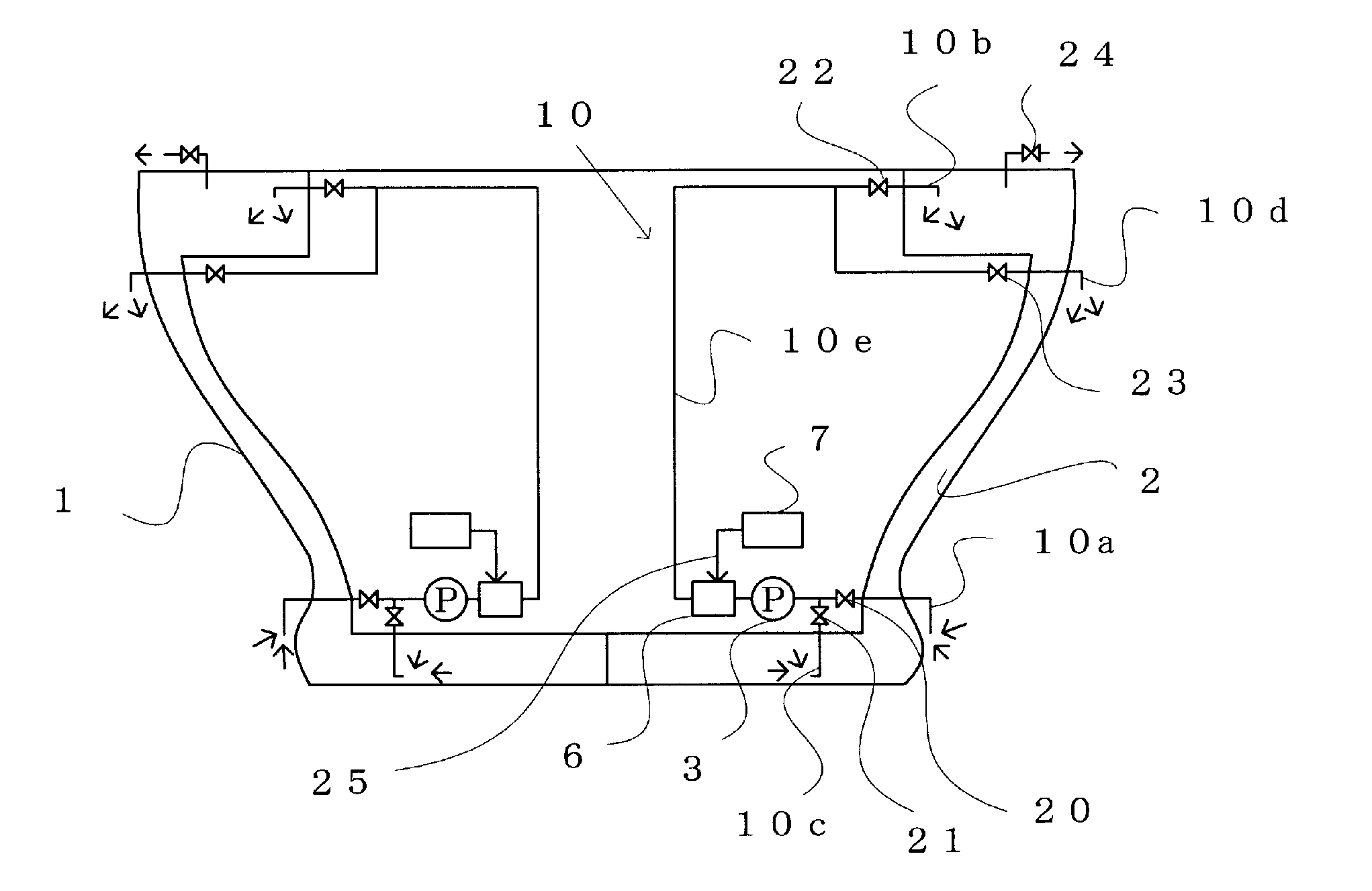
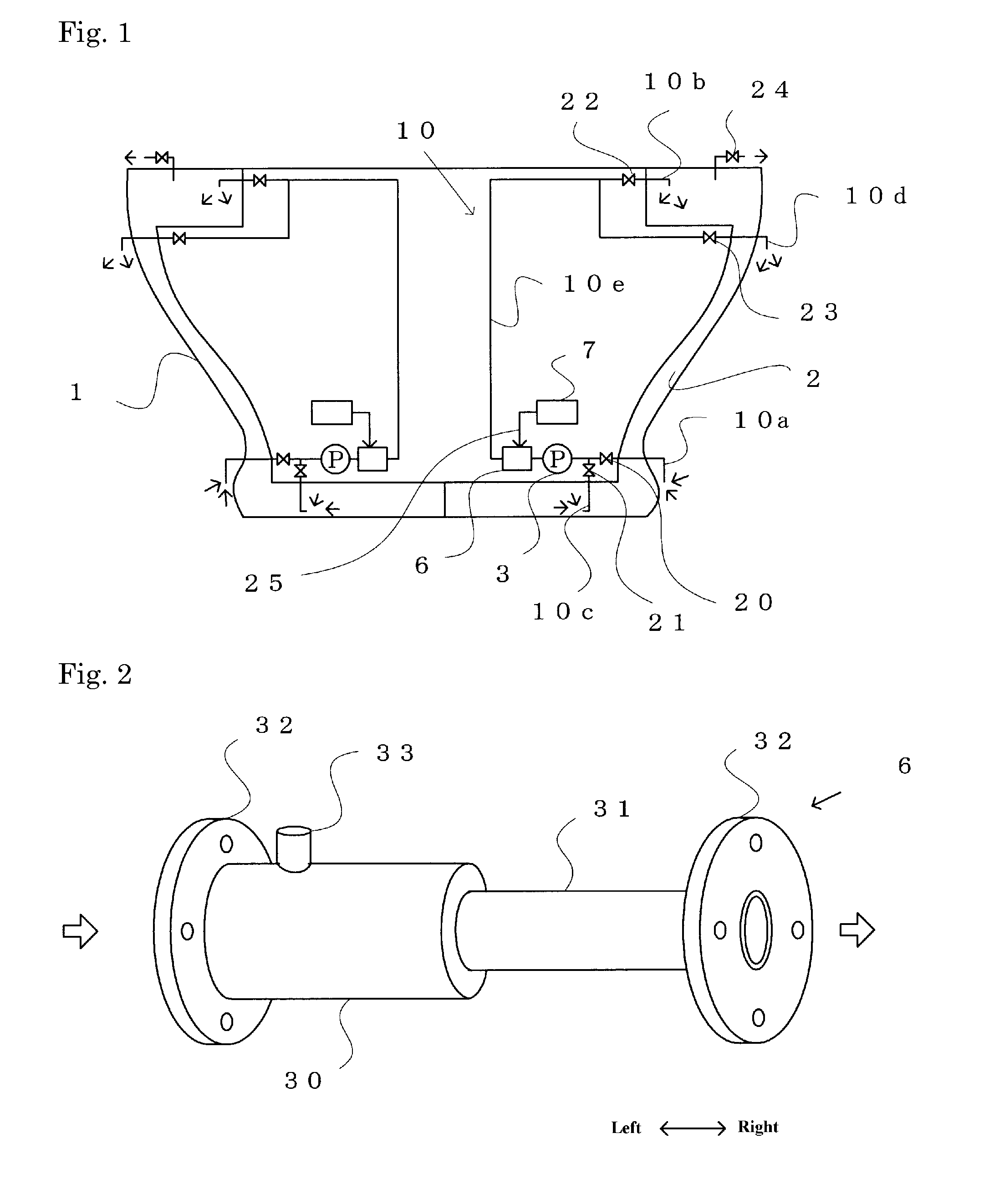
[0088]FIG. 1 shows the configuration of a ship's ballast-water sterilization system. The ship 1 is a double-hull type, having double sides and a double bottom that form a ballast tank 2. The ballast tank 2 is referred to as a top tank, a bilge tank, and a bottom tank, when viewed from the side, and is partitioned into right and left portions based on the center of the ship's bottom. A pipeline 10 for supplying water into, and discharging ballast water from, the ballast tank 2 has two routes. Here, the right-side portion of FIG. 1 is referred to. When the ballast water is supplied to the ballast tank 2, the ballast pump 3 opens valves 20 and 22, closes valves 21 and 23, opens valve 24 so that the air or the spilled ballast water in the ballast tank 2 is released to the outside, pumps seawater from the sea via the outside end of the pipe 10a, sterilizes it with the in-line mixer 6, and supplies the ballast water to the top of the ballast tank 2 through the pipes 10e and 10b. When the ...


PUM

PropertyMeasurementUnit
sizeaaaaaaaaaa
diameteraaaaaaaaaa
diameteraaaaaaaaaa

Abstract

A ballast-water treating apparatus that improves the performance of an in-line mixer so as to be able to sterilize a large volume of ballast water within a short period of time. There is provided a ballast-water treating apparatus that includes pipelines for feeding water to a ship's ballast tank(s) and for draining water from the ballast tank(s), ballast pumps on the pipelines, an ozone generator or hydrogen peroxide generator, a gas / liquid injection pipe for introducing generated ozone or hydrogen peroxide into the pipelines; and an in-line mixer that has two blades disposed crosswise in a tubular part composed of a main tubular part, a subsidiary tubular part that has an inside diameter smaller than that of the main tubular part and that is furnished with multiple projections, and a tapered part. The ballast-water treating apparatus can simultaneously carry out mechanical destructive sterilization via a swirling flow and sterilization of chemically active substances by micromixing.

Description

FIELD OF THE INVENTION[0001]The present invention relates to a ballast-water treating apparatus, and more particularly, to a ballast-water treating apparatus that can sterilize microorganisms in ballast water when the ballast water is obtained by pumping seawater into a ballast tank of a ship, or when the ballast water is discharged from a ship's ballast tank into the sea.BACKGROUND OF THE INVENTION[0002]Normally, seawater is used for ballast water and, as a result, a large amount of bacteria and microorganisms living in the sea are present in the seawater used as the ballast water. When this ballast water is discharged into the seawater at a different location such as a ship's destination, a large amount of normative microorganisms are discharged in the seawater at that destination, which adversely impacts the ecological system in that area.[0003]One method to prevent such adverse impact on the ecological system is—while a ship is at sea during its voyage—to exchange the ballast wa...

Claims


Application Information

Patent Timeline
Patent Type & Authority Applications(United States)
IPC IPC(8): C02F1/72C02F1/50C02F1/78B01F5/00B01F5/04B63B13/00
CPCB01F3/0446C02F2303/04B01F5/0415B01F5/0451B01F5/061B01F5/0618B01F5/0646B01F2005/0441B01F2005/0621B01F2005/0636B63B13/00B63J4/002B63J4/004C02F1/34C02F1/722C02F1/78C02F2103/008B01F3/0865B01F23/232B01F23/451B01F25/312522B01F25/3121B01F25/3131B01F25/4317B01F25/4316B01F25/431B01F25/431971B01F25/433
Inventor UEMATSU, HIDETO
Owner OHR LAB CORP
Why Eureka
Try Eureka