Edge adjustment method, image processing device and display apparatus

Active Publication Date: 2010-02-11
EIZO
View PDF8 Cites 20 Cited by
  • Summary
  • Abstract
  • Description
  • Claims
  • Application Information

AI Technical Summary

Problems solved by technology

For instance, when the enhancement degree is set such that enhancement of the edge suited to the up converted image can be carried out, the edge of the image may be enhanced in excess and the quality of the displayed image may degrade if the edge of the HD image is enhanced in such setting.
When the enhancement degree is set such that enhancement of the edge suited to the HD image can be carried out, the edge of the image may not be sufficiently enhanced if the edge of the up converted image is enhanced in such setting.
However, the maximum luminance difference acquired from the input image may not necessarily be equal to the max

Method used


Image

  • Edge adjustment method, image processing device and display apparatus
  • Edge adjustment method, image processing device and display apparatus
  • Edge adjustment method, image processing device and display apparatus

Examples


first embodiment

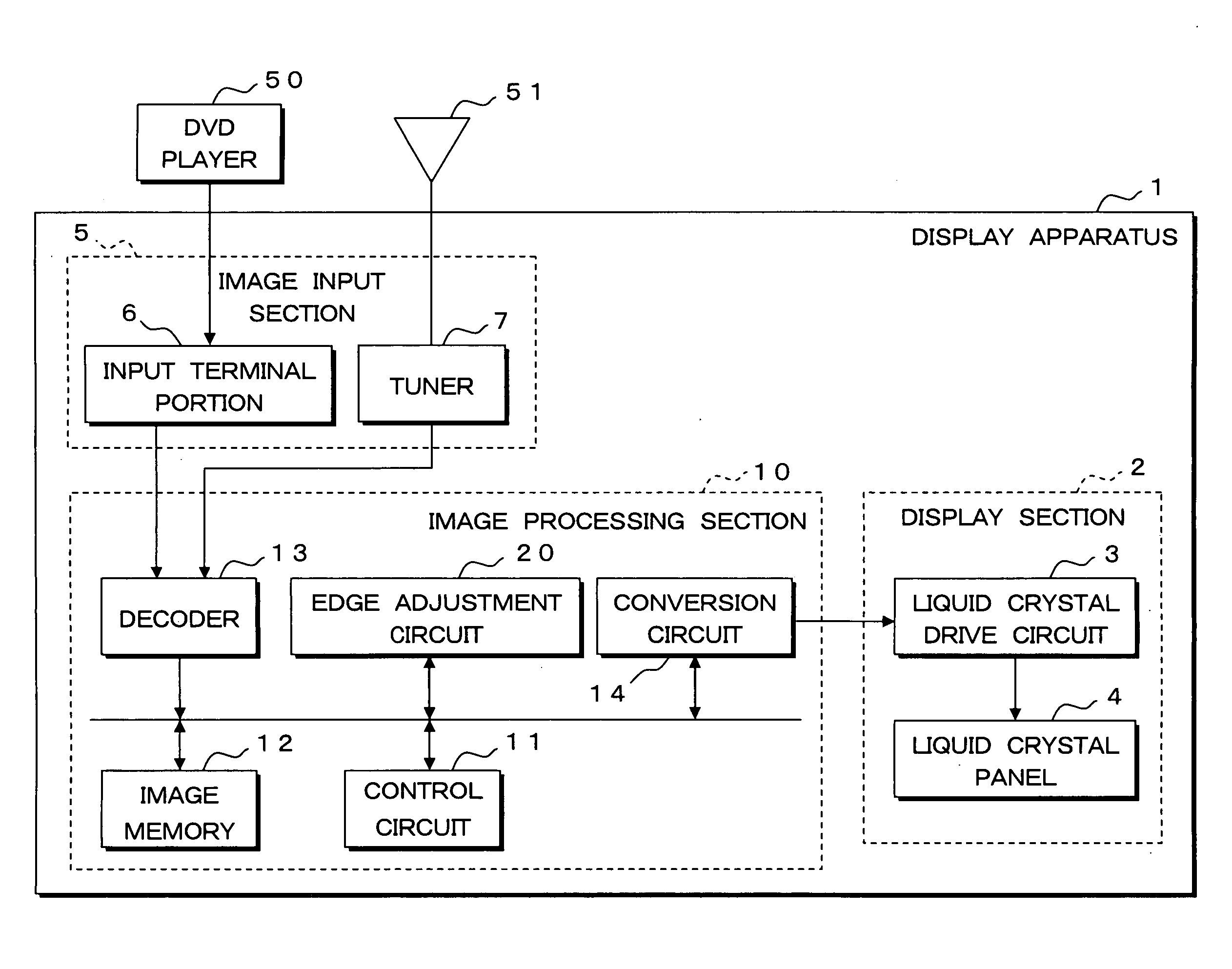
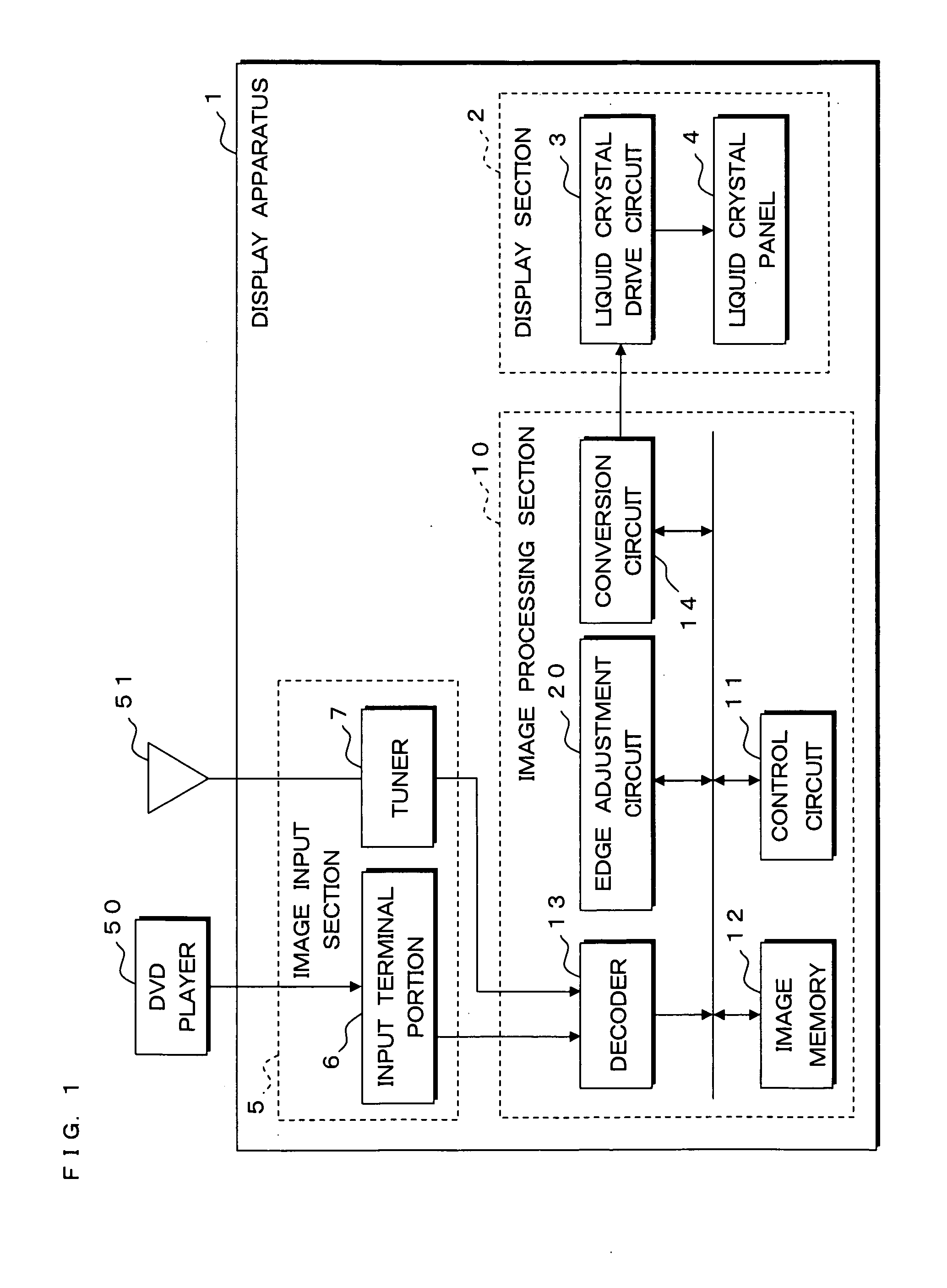
[0057]The present invention will be specifically described based on the drawings showing the embodiments thereof FIG. 1 is a block diagram showing a configuration of a display apparatus according to the present invention. Number 1 in the figure denotes a display apparatus for displaying images provided from a DVD player 50, images related to television broadcast received at an antenna 51, and the like on a liquid crystal panel 4. The display apparatus 1 includes a display section 2 for displaying images by means of the liquid crystal panel 4, an image processing section 10 for providing a signal related to the image to display to the display section 2, and an image input section 5 for inputting images provided from the DVD player 50, images received at the antenna 51, and the like to the image processing section 10.

[0058]The image input section 5 includes an input terminal portion 6 provided with a plurality of terminals such as HDMI (High Definition Multimedia Interface) and DVI-I ...

second embodiment

[0094]FIG. 8 is a block diagram showing a configuration of an edge adjustment circuit 120 of a display apparatus according to a second embodiment of the present invention. The edge adjustment circuit 20 of the first embodiment includes the average luminance calculating unit 22 for calculating the average luminance of the input image, but the edge adjustment circuit 120 of the second embodiment includes a proportion calculating unit 122 for calculating the proportion of the pixel which luminance value is greater than or equal to a predetermined luminance in the input image in place of the average luminance calculating unit 22. The proportion calculating unit 122 compares the luminance value of each pixel of the input image with a predefined threshold value, and counts the number of pixels of the pixels that luminance value is greater than the threshold value. The proportion can be calculated by performing the comparison with the threshold value for all the pixels of the input image, ...

third embodiment

[0098]FIG. 10 is a block diagram showing a configuration of an edge adjustment circuit 220 of a display apparatus according to a third embodiment of the present invention. The edge adjustment circuit 20 of the first embodiment includes the average luminance calculating unit 22 for calculating the average luminance of the input image, but the edge adjustment circuit 220 of the third embodiment includes a histogram generating unit 222 for generating a histogram showing the distribution of the luminance values in the input image in place of the average luminance calculating unit 22. The histogram generating unit 222 acquires the luminance value of each pixel of the input image, generates a histogram by tabulating the number of pixels for every luminance value, and provides the same to the control circuit 11.

[0099]FIG. 11 is a schematic view showing one example of a histogram generated by the histogram generating unit 222. In the illustrated example, the number of pixels in the input im...


PUM


Abstract

A noise removing filter removes noise from an input image and an edge component extracting unit extracts edge components. The edge components are extracted by calculating a difference between the input image and a smoothed image, which is obtained by smoothing the input image in a smoothed image generating portion. An edge component comparing unit compares the extracted edge components with a threshold value and a sum calculating unit calculates the sum of the edge components greater than the threshold value. A control circuit determines, the enhancement degree of the edges based on the sum and averaged luminance of the input image calculated by an average luminance calculating unit. An enhancement degree adjustment unit adjusts the determined enhancement degree, and an edge component enhancement unit enhances the edge components based on this enhancement degree and adds it to the input image to perform edge enhancement processing.

Description

[0001]This application is the national phase under 35 U.S.C.§371 of PCT International Application No. PCT / JP2007 / 65055 which has an International filing date of Aug. 1, 2007 and designated the United States of America.BACKGROUND[0002]1. Technical Field[0003]The present invention relates to an edge adjustment method for performing adjustment such as edge enhancement suited to the characteristics of the input image, an image processing device for performing edge adjustment on the input image by using such method, and a display apparatus, mounted with the image processing device, for displaying the image performed with the edge adjustment.[0004]2. Description of Related Art[0005]Conventionally, a liquid crystal display device for displaying images with a liquid crystal panel is being widespread used as one of the display devices. The liquid crystal display device has an advantage over the display device with a cathode ray tube in that a large and thin display device can be realized. A ...

Claims


Application Information

Patent Timeline
IPC IPC(8): G09G5/00G06K9/40
CPCG06T5/002G06T5/004H04N5/208H04N5/142G06T2207/20192G06T5/00
Inventor UENO, KOICHIKATSURA, MASANORIWATANABE, KAZUYUKIKOBAYASHI, YASUHIROTANAKA, KIYOYUKI
Owner EIZO
Why Eureka
Try Eureka