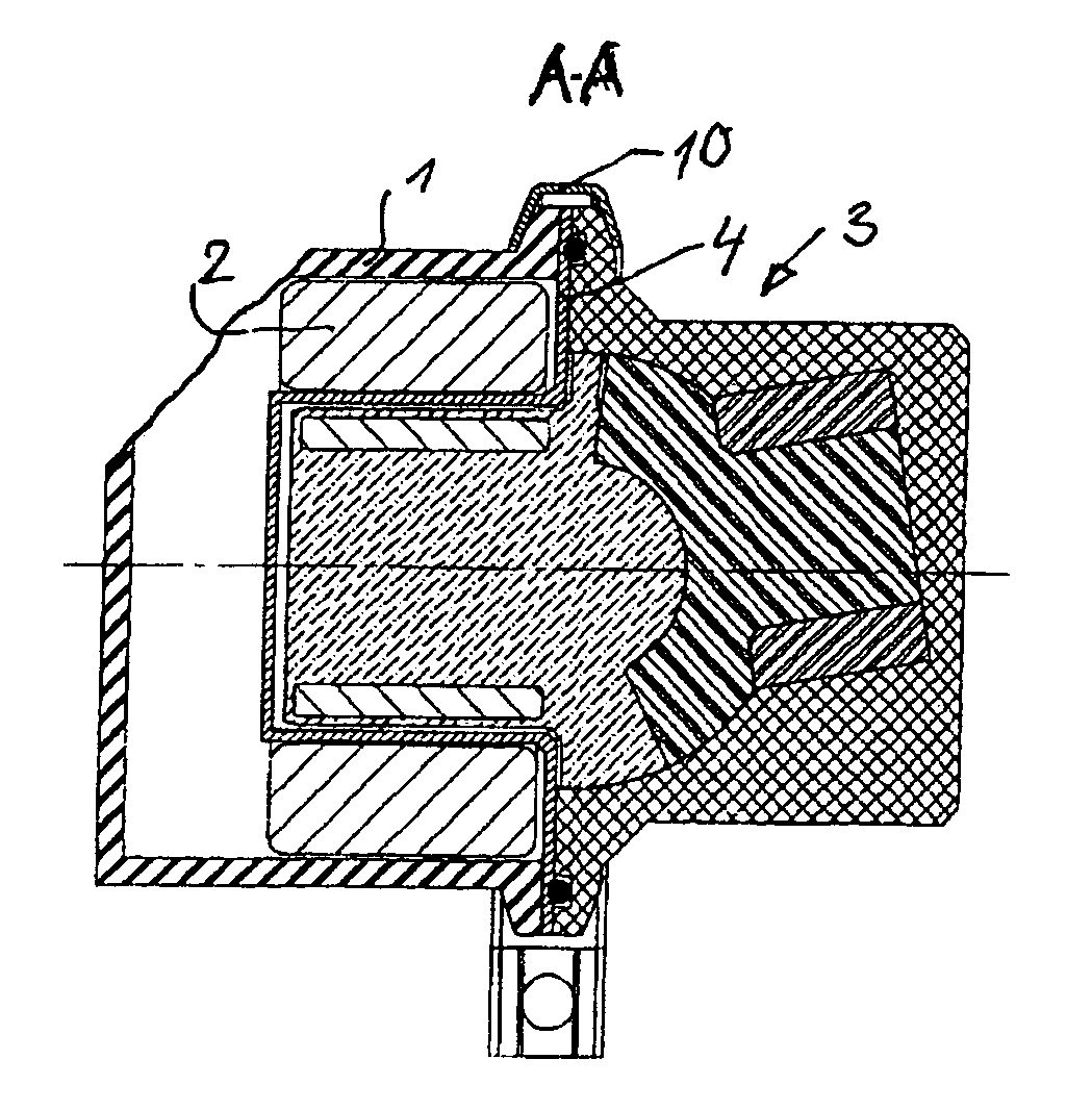
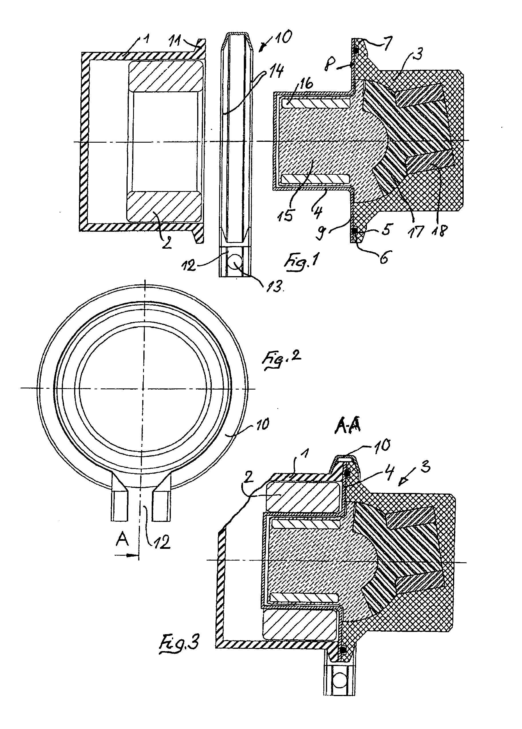
[0003]The object on which the invention is based in a rotary piston machine of the generic type is to develop a deployment method or manufacturing method, or a
special design by means of which such a rotary piston machine can be made available to a wide range of use, in particular while overcoming the prejudices of the specialists.
[0011]According to one advantageous refinement of the invention, when the
pump head is replaced as a disposable part, the can with rotors and permanent
magnet is therefore pulled out of the basic housing, after which the replacement part is then inserted. In order to facilitate the inventive replacement of the pump head, according to one refinement of the invention the connection between the basic housing and the pump head is embodied as a quick-action
coupling which acts on corresponding devices of the basic housing and pump head.
[0005]It is known per se for the usually fixedly arranged, complex housing part which accommodates the electrically controlled coil and through which current flows in an electrically driven pump to be separated by means of a cup-shaped can from the rotating power rotor which accommodates the permanent
magnet (DE 603 00 780 T2 and AT 28 11 84), but said document is concerned with a completely different problem, specifically with the cooling of electrical parts of such can pumps and not, as is the case in the invention, with a cost-saving configuration by combining an “inexpensive” pump head which is provided as a disposable part with a complex pump housing, which is under certain circumstances locationally fixed. The important thing for the invention is that after the pump head is released from the basic housing, the working spaces through which the medium which is to be fed flows are closed off on the side facing the basic housing so that, for example, acids and the like can remain in the disposable part and can be disposed of with it. In the known can motors (DE 603 00 780 D2 and AT 28 11 84), only the split cup dips into the electrically controlled winding when the pump is in the
closed state, but the housing which holds the current coil does not form basic housing so that when the part which holds the coil through which
electricity flows is moved the pump head is no longer closed with respect to the media to be fed.
[0006]It is also known to make the pump unit and motor or the operative connection between the motor and pump releasable in a medical
metering pump for liquid medicines, in order, in so far as the pump is concerned, to thereby obtain a disposable unit which can be disconnected from the expensive drive unit (
electric motor) so that the latter can be re-used (DE 199 16 876 A1). However, the pump here is a hose pump in which the feature according to which the pump head is embodied as a disposable part can already be found, but said hose pump does not have a quick-action connection apart from the fact that, of course, such pumps which are sealed off from the outside only by the feed hose have a very
narrow range of use, and said pump is to be assigned to a different generic type of pumps with respect to the invention.
The solution which arises from the problem on which the invention is based, specifically for the pump head which is composed of trochoidal parts to be embodied as disposable part and for said disposable part therefore to be connected to the basic housing with a quick-action connection, is unusual for a person skilled in the art, while quick-action connections between the motor and specific pumps of a wide variety of types are known, as is mentioned above.
Only a very small number of known rotary piston machines meet the requirement for a damaging space which tends towards zero, which is very difficult to achieve (DE AS 10 11 896, NSU; WO 2005 / 024236 A1, COR), and they meet this requirement by virtue of the fact that the teeth of the rotating parts are embodied in cycloidal or trochoidal form and engage in the teeth of the other rotating part in a seal-forming fashion without additional sealing means by virtue of
rounding of the teeth. In these known rotary piston machines, the damaging space can therefore be reduced to zero.
[0008]Although such a rotary piston machine with a rotor which is embodied in a trochoidal form has the
advantage of a small damaging space, it does therefore not yet solve the abovementioned problem, in particular when materials are fed at high temperatures (plastics) or aggressive materials are fed.
The solution which arises from the problem on which the invention is based, specifically for the pump head which is composed of trochoidal parts to be embodied as disposable part and for said disposable part therefore to be connected to the basic housing with a quick-action connection, is unusual for a person skilled in the art, while quick-action connections between the motor and specific pumps of a wide variety of types are known, as is mentioned above.
[0010]A rotary piston machine which is to be configured according to claim 3 and has a can embodied in the form of a cup in order to facilitate replacement of the pump head constitutes an additional intellectual step which is unusual because the pump head through which the substrate to be fed flows does not form, by virtue of its replaceability according to the invention, a connection, in terms of ideas, to the function of the known canned motor since for a person skilled in the art of the known pumps the can is intended to separate hermetically the flowing medium from the electrical part of the pump part during operation.
[0011]According to one advantageous refinement of the invention, when the pump head is replaced as a disposable part, the can with rotors and permanent
magnet is therefore pulled out of the basic housing, after which the replacement part is then inserted. In order to facilitate the inventive replacement of the pump head, according to one refinement of the invention the connection between the basic housing and the pump head is embodied as a quick-action
coupling which acts on corresponding devices of the basic housing and pump head.
[0012]An advantageous refinement of the invention in this respect is such
[0014]that the housings in the region which is in contact have an outer bead or
flange, which are assigned to one another, and
[0015]that the housings can be clamped together axially by means of a ring which engages over these beads or flanges and can be shortened tangentially.
[0016]One refinement of the invention consists in a manufacturing method in which these plastic parts of the pump head and / or of the split cup are manufactured ready-from-the mold. Such a method of manufacture can be used particularly advantageously in the trochoidally toothed rotors in which rounded teeth run on smooth faces with positive engagement, bounding a linear
working space, between the edges and tooth tines of the teeth
lying opposite one another, which is at
odds with ready-from-the mold manufacture including the housing parts of the pump head and split cup.

