
Flat light concentration device with reduced thickness

a technology of light concentration device and flat surface, which is applied in the direction of solar heat device, lamination, photovoltaics, etc., can solve the problems of large optical distance of these devices, bulky devices, and inability to obtain, and achieve the effect of increasing the efficiency of light concentration devi

Inactive Publication Date: 2010-02-18
COMMISSARIAT A LENERGIE ATOMIQUE ET AUX ENERGIES ALTERNATIVES
View PDF6 Cites 41 Cited by
  • Summary
  • Abstract
  • Description
  • Claims
  • Application Information

AI Technical Summary

Benefits of technology

[0014]Another aim of the invention is to propose a light concentration device that is simple to produce and therefore inexpensive.
[0030]The light concentration device has a rear face that is a face of the diffraction grating situated opposite to the principal face having the lowest refractive index of the plate, the rear face can be provided with a reflective or semi-reflective rear coating. The efficiency of the light concentration device is thus increased.
[0037]A front protection device can be placed against the main face having the lowest refractive index of the plate or at least one of the plates. It is thus possible to use plastics material for the plate even if this plastics material does not age well.
[0054]In a variant, it is possible to form the plate or at least one of the plates by assembling a plurality of strips so as to obtain a stack, these strips having different refractive indices, and then by heating the stack until fusion so as to eliminate the interfaces between the strips by interdiffusion.

Problems solved by technology

The focal distances of these devices are great.
These devices are bulky and do not make it possible to obtain, when they are associated with a photovoltaic cell, an assembly with an acceptable thickness for a domestic application.
In parabolic-mirror devices, the photovoltaic cell is placed at the focus of the parabolic mirror, which renders electrical contact and cooling of the cell difficult.
It has significant variations in thickness in the zones and edges with acute angles that are not necessarily easy to achieve.
Moreover, the illumination received by the photovoltaic cell is not uniform and this is detrimental to the efficiency of the latter and its service life.
Such integrated concentration devices are less bulky but this is achieved at the cost of increased complexity of the optical surfaces.
In addition, such light concentration devices have a very small acceptance angle, limited to approximately 1° to 3°.
The smaller the acceptance angle, the greater must be the precision of the mechanical device and the more expensive this device is.
In these devices, the front face of the optical components must be protected and this protection is difficult or even impossible to achieve.
Integration thereof in very large solar panels is difficult and these devices appear to be more suitable for use in centralised energy production, in solar farms, in which a plurality of solar panels of medium size are coupled.
It is also perceived that these light concentration devices have mediocre performance in diffuse lighting, in particular when the sky is cloudy, and can be used effectively only in very sunny areas.

Method used


Image

  • Flat light concentration device with reduced thickness
  • Flat light concentration device with reduced thickness
  • Flat light concentration device with reduced thickness

Examples


Embodiment Construction

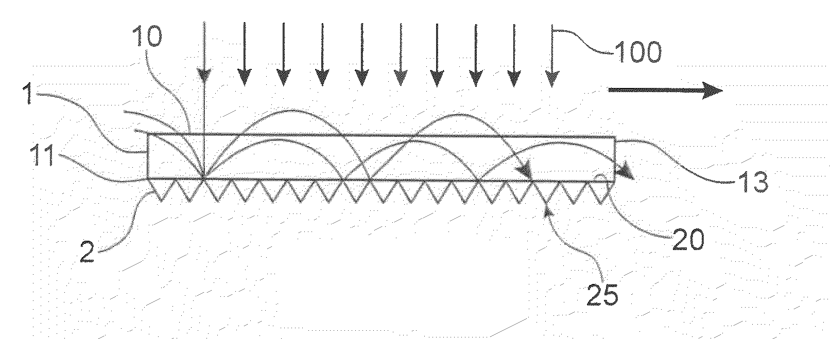
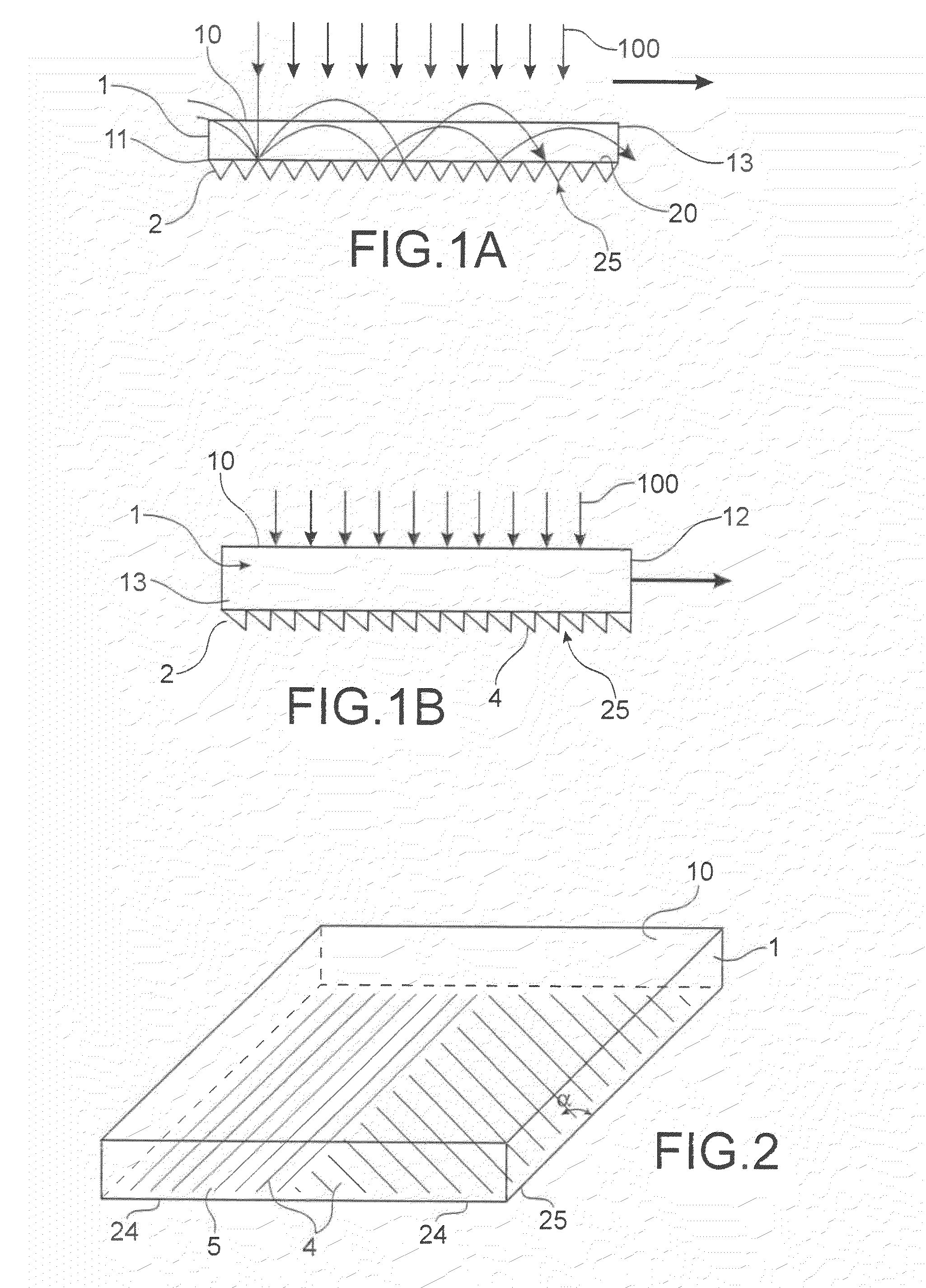
[0075]A description will now be given, with reference to FIG. 1A, of a first example of a light concentration device according to the invention. This light concentration device comprises at least one plate 1 with a refractive index gradient and at least one diffraction grating 2. The diffraction grating 2 is reflective or semi-reflective.

[0076]Plate means a sheet allowing light to pass, having two substantially flat parallel principal faces 10, 11 and an edge 13. The face referenced 10 is said to be the front face of the light concentration device. The plate with a refractive index gradient 1 and the diffraction grating 2 are up against each other. The other principal face 11 of the plate 1 and a principal face 20 of the diffraction grating 2 form an interface between the diffraction grating 2 and the plate 1. The other face 25 of the refraction grating forms the rear face of the light concentration device.

[0077]The refractive index of the plate 1 increases along the thickness of th...


PUM

PropertyMeasurementUnit
acceptance angleaaaaaaaaaa
thicknessaaaaaaaaaa
thicknessaaaaaaaaaa

Abstract

A light concentration device includes: a plate including two principal faces and an edge between the two principal faces, a refractive index gradient existing between the two principal faces, and a diffraction grating functioning in reflection or semi-reflection that cooperates with one of the principal faces of the plate having the highest refractive index, the principal face having the lowest refractive index forming a front entry face for the light, at least one exit zone for the light being disposed on the edge.

Description

TECHNICAL FIELD[0001]The present invention relates to a flat light concentration device with reduced thickness. Such a device can be associated with a photovoltaic cell or be used independently in the field of natural or artificial lighting. The use of a light concentration device in a photovoltaic device makes it possible to reduce the surface area of the photovoltaic cell for the same surface illuminated by the sun. It therefore reduces the cost of the energy produced.PRIOR ART[0002]Conventional light concentration devices, which are not intended to transform the solar spectrum, use Fresnel lenses or parabolic mirrors.[0003]In both cases, these optical components are said to be primary and cooperate with secondary optical components also of the lens or mirror type. The focal distances of these devices are great. These devices are bulky and do not make it possible to obtain, when they are associated with a photovoltaic cell, an assembly with an acceptable thickness for a domestic a...

Claims


Application Information

Patent Timeline
Patent Type & Authority Applications(United States)
IPC IPC(8): H01L31/00G02B27/44B29C35/08B29C59/04B29C59/00B44C1/22B29C65/00G03F7/00F24S23/30F24S23/70
CPCY02E10/52H01L31/0547Y10T156/10
Inventor THONY, PHILIPPE
Owner COMMISSARIAT A LENERGIE ATOMIQUE ET AUX ENERGIES ALTERNATIVES
Features
  • Generate Ideas
  • Intellectual Property
  • Life Sciences
  • Materials
  • Tech Scout
  • Unparalleled Data Quality
  • Higher Quality Content
  • 60% Fewer Hallucinations
Learn More