Interlaced multi-energy radiation sources

a radiation source and interconnection technology, applied in the field of radiation sources, can solve the problems of slow frequency drift of the accelerator resonance frequency, small mismatch between the frequency of a magnetron and the resonance frequency of the accelerator, and the critical problem of cargo container inspection at national borders, seaports, and airports, etc., to achieve the effect of improving the frequency control

Active Publication Date: 2010-02-18
VAREX IMAGING CORP
View PDF44 Cites 69 Cited by
  • Summary
  • Abstract
  • Description
  • Claims
  • Application Information

AI Technical Summary

Benefits of technology

[0013]A single accelerator may accelerate beams of electrons or other charged particles to different energies by being excited at two different RF power levels by the RF power generator. It may be necessary to rapidly switch the power generator between generation of two power levels. Switching on the order of a millisecond may be desirable, for example. As the RF power varies pulse to pulse, the frequency of the RF power pulses, as well

Problems solved by technology

The inspection of cargo containers at national borders, seaports, and airports is a critical problem in national security.
The RF power provided to the accelerator causes heating and expansion of the accelerator structure, which causes a slow frequency drift of the accelerator resonance frequency.
Such drift is most noticeable in the first minute or two of operation, but may continue due to environment conditions.
When a magnetron is used, pulse to pulse frequency jitter in the magnetron may

Method used


Image

  • Interlaced multi-energy radiation sources
  • Interlaced multi-energy radiation sources
  • Interlaced multi-energy radiation sources

Examples


Embodiment Construction

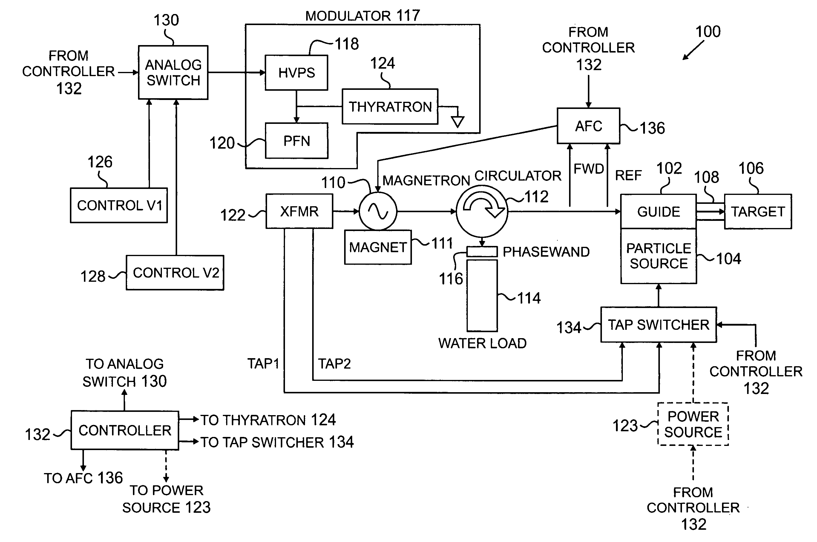
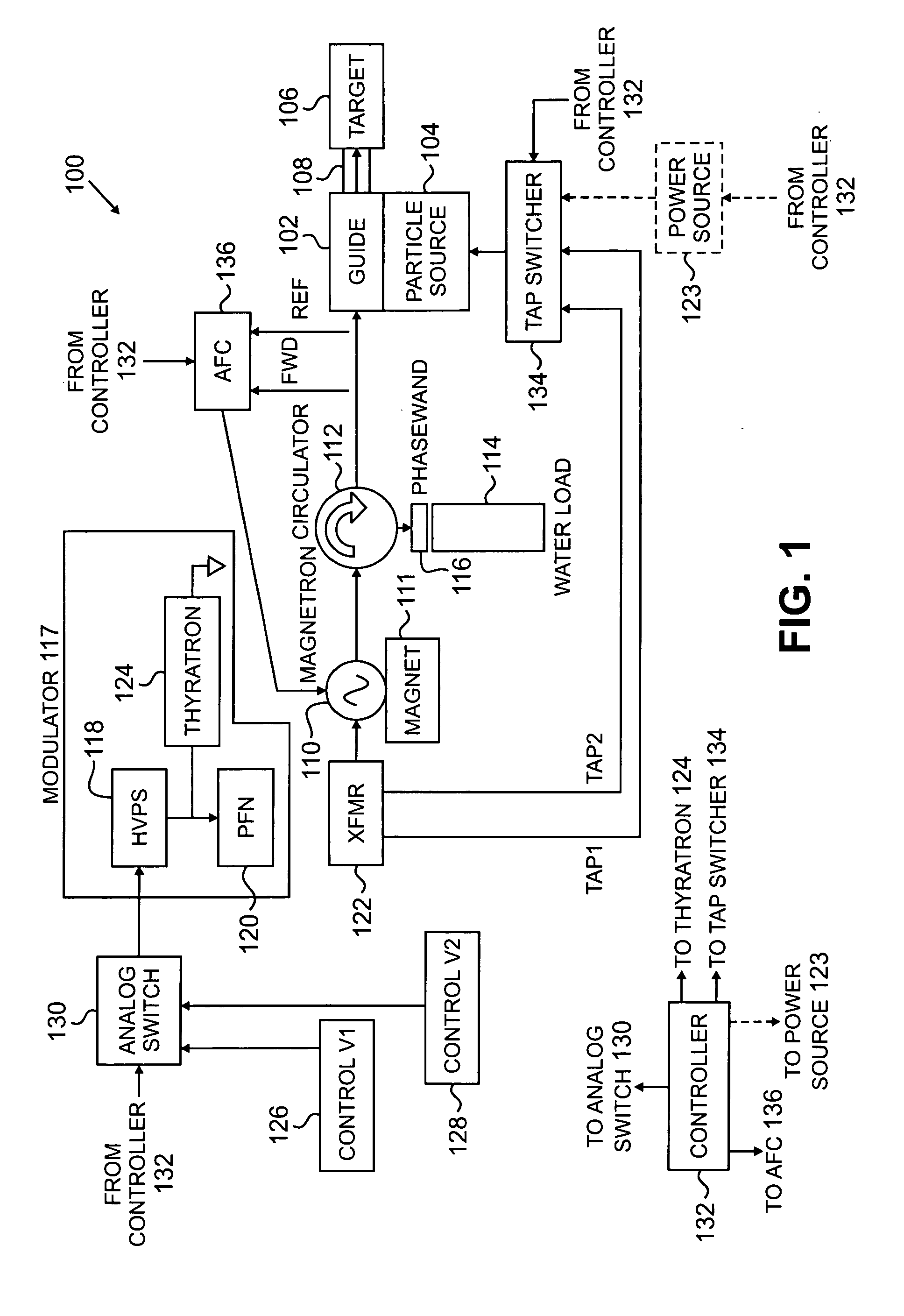
[0029]FIG. 1 is a schematic diagram of an example of multi-energy radiation source 100 in accordance with an embodiment of the invention. In this example, the radiation source 100 is configured to accelerate charged particles, such as electrons, to first and second nominal energies in an interlaced manner, and collide the accelerated charged particles with a target to generate radiation having two different energy spectra, one having a high energy, and another having a low energy, in an interlaced manner. In one example, the first nominal electron energy is 6 MeV, which causes generation of a 6 MV radiation beam (high energy in this example), and the second nominal energy is 3.5 MeV, which causes generation of a 3.5 MV radiation beam (low energy in this example), at a pulse rate of 200 or 300 pulses per second (“pps”). Other combinations of energies may be generated, such as 9 MV and 6 MV, at lower or higher pulse rates. The pulse rate may be 400 pps, for example. More than two radi...


PUM


Abstract

Multi-energy radiation sources comprising charged particle accelerators driven by power generators providing different RF powers to the accelerator, capable of interlaced operation, are disclosed. Automatic frequency control techniques are provided to match the frequency of RF power provided to the accelerator with the accelerator resonance frequency. In one example where the power generator is a mechanically tunable magnetron, an automatic frequency controller is provided to match the frequency of RF power pulses at one power to the accelerator resonance frequency when those RF power pulses are provided, and the magnetron is operated such that frequency shift in the magnetron at the other power at least partially matches the resonance frequency shift in the accelerator when those RF power pulses are provided. In other examples, when the power generator is a klystron or electrically tunable magnetron, separate automatic frequency controllers are provided for each RF power pulse. Methods and systems are disclosed.

Description

FIELD OF THE INVENTION[0001]This invention relates generally to radiation sources, and more specifically, to interlaced multiple energy radiation sources.BACKGROUND OF THE INVENTION [0002]Radiation is commonly used in the non-invasive inspection of contents of objects, such as luggage, bags, briefcases, cargo containers, and the like, to identify hidden contraband at airports, seaports, and public buildings, for example. The contraband may include hidden guns, knives, explosive devices, illegal drugs, and Special Nuclear Material, such as uranium and plutonium, for example. One common inspection system is a line scanner, where the object to be inspected is passed through a fan beam or pencil beam of radiation emitted by a source of X-ray radiation. Radiation transmitted through the object is attenuated to varying degrees by the contents of the object and detected by a detector array. Attenuation is a function of the type and amount (thickness) of the materials through which the radi...

Claims


Application Information

Patent Timeline
IPC IPC(8): G01J1/00
CPCH01J2235/08H05H7/02H05H2007/025H05H9/048H05H2007/022H05H9/00
Inventor CHEN, GONGYINTURNER, JOHNEATON, DOUGLAS W.
Owner VAREX IMAGING CORP
Why Eureka
Try Eureka