Rotating electric machine and cooling system for the rotating electric machine

a technology of rotating electric machines and cooling systems, which is applied in the direction of rotating parts of magnetic circuits, magnetic circuit shapes/forms/construction, windings, etc., can solve the problems of increasing the cost of manufacturing motors, the weight of rotating electric machines or and the increase of the cost of manufacturing rotating electric machines. , to achieve the effect of improving the heat discharging properties of stator coil ends

Active Publication Date: 2010-02-18
TOYOTA JIDOSHA KK +1
View PDF10 Cites 23 Cited by
  • Summary
  • Abstract
  • Description
  • Claims
  • Application Information

AI Technical Summary

Benefits of technology

[0032]As described above, by employing the rotating electric machine and the cooling system for the rotating electric machine according to the present invention, effective improvement of the heat discharging properties of the stator coil end can be achieved.

Problems solved by technology

However, with either of these approaches, undesirable increase in either or both of the weight of the rotating electric machine or the cost of manufacture of the rotating electric machine is brought.
Further, fixing separate ribs to the bracket undesirably increases the cost of manufacturing the motor.
In the case of the rotating electric machine disclosed in JP-A-2005-73351 described above, because the cooling oil holding member used only for cooling the rotating electric machine is provided in the housing, the cost of manufacturing the rotating electric machine is undesirably increased.
Also, in the case of the motor disclosed in JP-A-2005-354821 as described above, forming the notched portion for defining the coolant flow channel on the resin molded portion, and providing the coolant discharging hole penetrating through the resin molded portion both undesirably increase the manufacturing cost of the motor might be resulted.
In the case of the motor disclosed in JP-A1-2004 / 19468 as described above, providing the coil end cover which surrounds both end surfaces of the coil of the stator unit and the stator core undesirably increases the cost of manufacturing the motor.

Method used


Image

  • Rotating electric machine and cooling system for the rotating electric machine
  • Rotating electric machine and cooling system for the rotating electric machine
  • Rotating electric machine and cooling system for the rotating electric machine

Examples


first embodiment

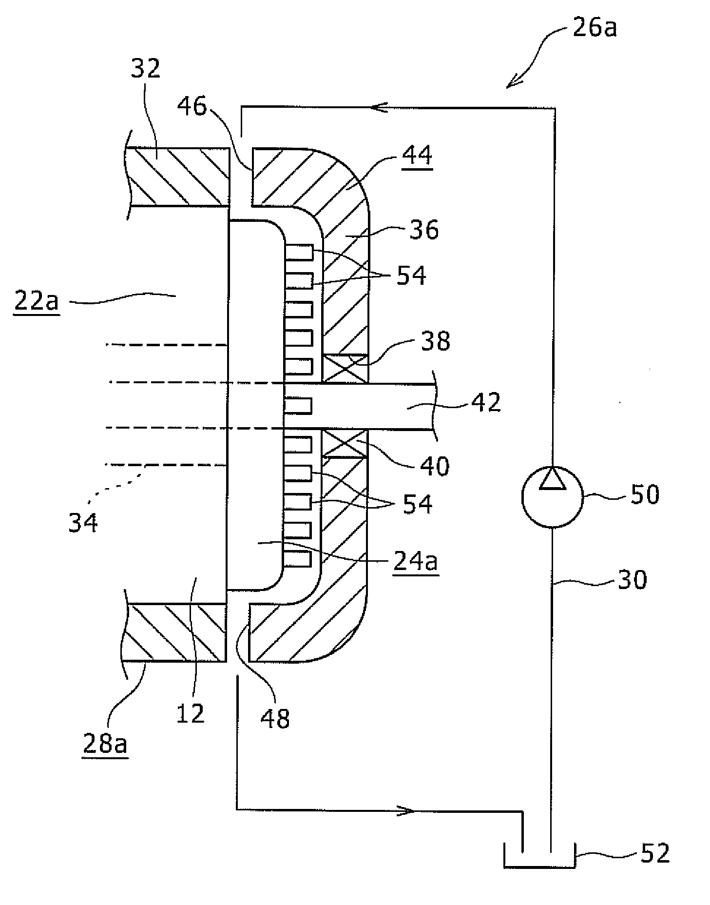
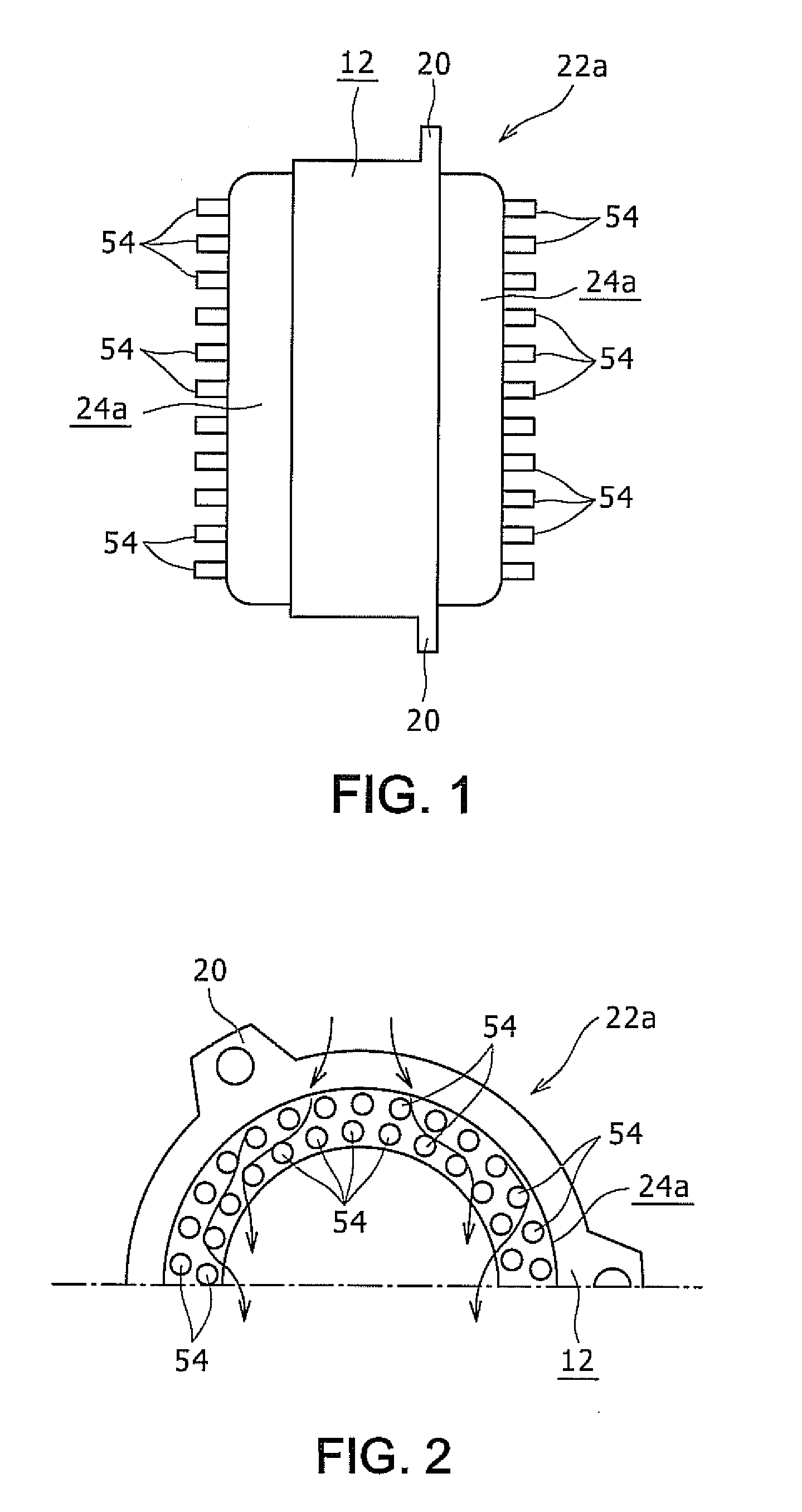
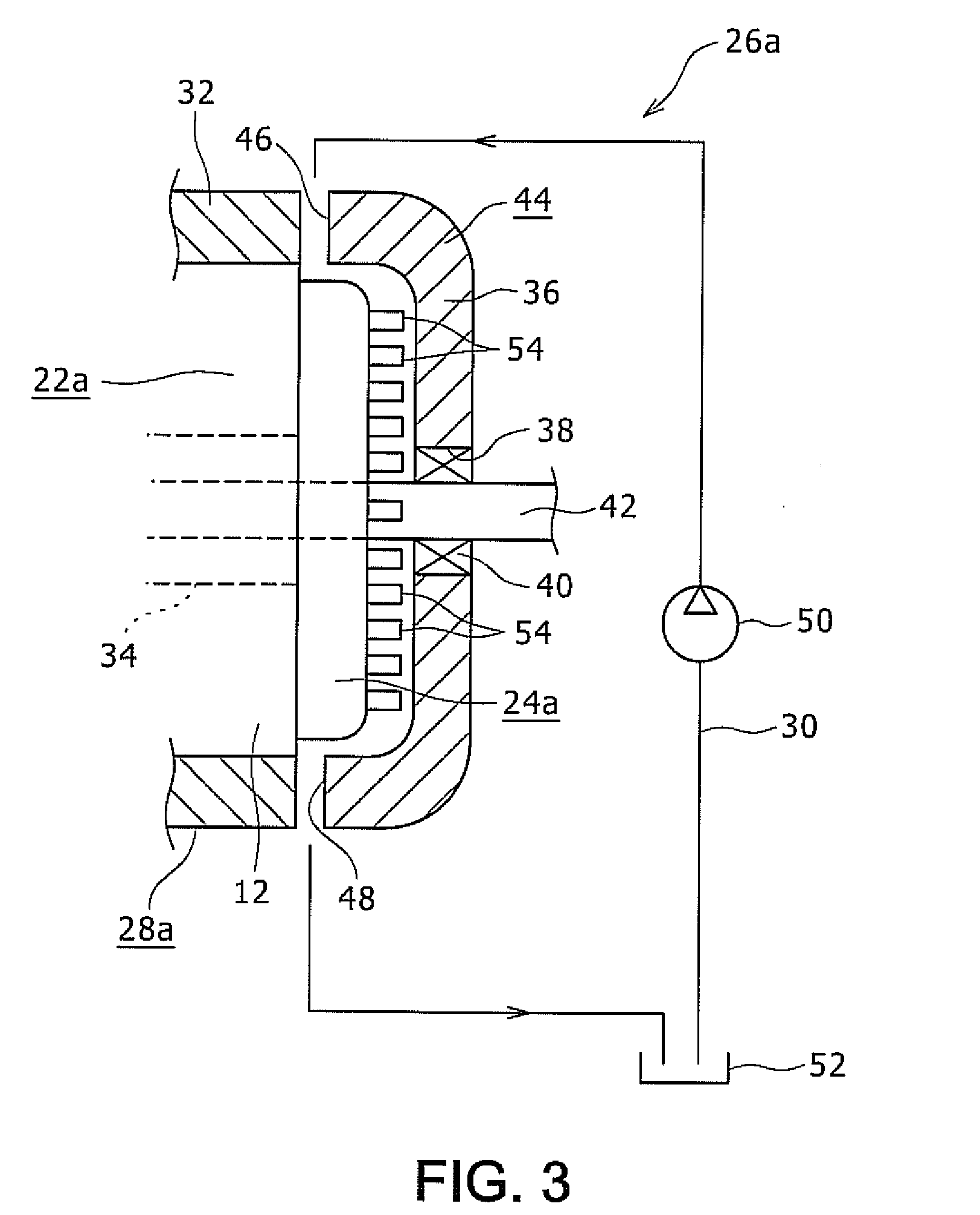
[0046]A first embodiment of the present invention will be described with reference to FIGS. 1, 2, and 3. FIG. 1 is a schematic drawing showing a stator which constitutes a motor as a rotating electric machine according to the first embodiment. FIG. 2 is a drawing showing an upper half portion of the stator shown in FIG. 1 when viewed leftward from the right. FIG. 3 is a perspective view showing a cooling system for the rotating electric machine.

[0047]A motor 28a according to the first embodiment is used to drive, for example, a hybrid vehicle or to generate electricity, and includes a stator 22a shown in FIGS. 1 and 2 and a rotor 34 (see FIG. 3). The stator 22a includes a stator core 12 formed of a laminated steel plate or the like and a pair of resin mold coil ends 24a provided on axial both ends thereof. The stator core 12 is fixed inside a motor case 44 formed of a metal such as aluminum by die casting or the like as shown in FIG. 3. A rotary shaft 42 is disposed radially inside ...

second embodiment

[0059]FIG. 4 is a schematic drawing showing a stator which constitutes a motor as an example of a rotating electric machine according to a second embodiment of the present invention. FIG. 5 is a drawing showing an upper half portion of the stator shown in FIG. 4 when viewed from the right side. In the second embodiment, column-shaped projections 58 of a shaft shape projecting in the radial direction or in a direction inclined with respect to the radial direction are provided on an outer peripheral surface of a resin mold coil end 24b which constitutes a stator 56 at a plurality of positions in the circumferential direction. The column-shaped projections 58 are provided also at positions on the respective resin mold coil ends 24b separated from each other along the radial axis.

[0060]All of the plurality of column-shaped projections 58 positioned within a certain angular range shown by an angle α1 in FIG. 5 with respect to an axial center O (see FIG. 5) of the resin mold coil end 24b ...

third embodiment

[0066]FIG. 6 is a partial cross-sectional drawing showing a motor as an example of a rotating electric machine according to a third embodiment of the present invention. FIG. 7 is a drawing showing an upper half portion of a cover which constitutes the motor shown in FIG. 6 removed from its installation and viewed from the left side in FIG. 6. According to a motor 28b of the third embodiment, in a motor 28 as shown in FIG. 12 which includes the stator 22 conceived in the related art shown in FIGS. 9 to 11, an inner surface portion of a cover36a which constitutes the motor case 44 opposing the resin mold coil end 24 as the stator coil end is formed of foamed metal 60 as a foamed portion formed from a metal such as aluminum. The foamed metal 60 is provided on an inner peripheral surface of a cylindrical portion 62 which constitutes the bottomed cover 36a and an entire inner surface portion of a bottom panel portion 64 which covers an end portion of the cylindrical portion 62. The cover...


PUM


Abstract

Heat discharging property of the stator coil end is improved effectively in a rotating electric machine. A motor as the rotating electric machine includes a stator and a rotor. The stator includes a stator core and resin mold coil ends provided on both axial ends thereof. Column-shaped projections projecting in the axial direction are provided on axial side surfaces of resin mold coil ends at a plurality of positions. Cooling oil supplied from above the resin mold coil ends effectively cools the resin mold coil ends.

Description

RELATED APPLICATIONS[0001]This application claims priority to Japanese Patent Application No. 2008-207803, filed on Aug. 12, 2008, the entire content of which is incorporated herein by reference.BACKGROUND ART[0002]The present invention relates to a rotating electric machine having a rotor and a stator opposing the rotor and having a stator coil end, and a cooling system for the rotating electric machine.[0003]A rotating electric machine for a vehicle motor or the like known conventionally in the related art includes a stator and a rotor. As the stator which constitutes the rotating electric machine, a stator as shown in FIG. 8 is conceived in the related art. FIG. 8 is a schematic perspective view of a first example of the stator which is conceived in the related art. A stator 10 shown in FIG. 8 includes teeth 14 projecting in the radial direction on an inner peripheral surface of a stator core 12, which is configured with a laminated steel plate or the like, at a plurality of posi...

Claims


Application Information

Patent Timeline
Patent Type & Authority Applications(United States)
IPC IPC(8): H02K9/197H02K9/22
CPCH02K9/19H02K9/227
Inventor URANO, HIROAKIYAMADA, EIJITATEMATSU, KAZUTAKATAKETSUNA, YASUJIARAKAWA, ATOMITANAKA, AKIHIROONIMARU, SADAHISAMATSUI, HIROHITOOKAMOTO, RYOTARO
Owner TOYOTA JIDOSHA KK
Why Eureka
Try Eureka