Diode Loss Detection for Low Side MOSFET of a Synchronous Output Stage

Active Publication Date: 2010-02-18
INFINEON TECH AG
View PDF8 Cites 18 Cited by
  • Summary
  • Abstract
  • Description
  • Claims
  • Application Information

AI Technical Summary

Benefits of technology

[0010]In accordance with an exemplary embodiment, a process of protecting a power-processing device such as a switch-mode power converter that includes a diode coupled in series with an inductor and a related method are provided. A series arrangement of a resistor and a switch is coupled in parallel with the diode. The resistance of the resistor is preferably selected to be of the same order of magnitude as the on-resistance of the switch. In an embodiment, a first input terminal of a comparator is coupled to a first terminal of the resistor and a second input terminal of the comparator is coupled to a second terminal of the resistor. The comparator is configured to assert an output signal when a current through the resistor crosses a threshold current level, and a controller is configured to shut down the power-processing device in response to assertion of the output signal. In an embodiment, the switch is configured to carry a small fraction of the current carried by the diode when the diode is substantially forward biased. In an embodiment, the switch comprises an area of a semiconductor die less than 50% of the area of another switch formed on the semiconductor die. In an embodiment, the series arrangement of the resistor and the switch enable the power-processing device to operate in continuous conduction mode at substantially no load current. In an embodiment, the power-processing device is a switch-mode power converter.

Problems solved by technology

Separate components that are not easily integrated, such as a power diode, typically dissipate a substantial level of power, or are formed of materials and structures that are not easily integrated in a semiconductor device, such as an output filter inductor or an output filter capacitor.
Integrating a low-side power switch increases the size of the integrated circuit and increases the risk of latch up.
Failure to power down the power converter in such a circumstance can result in dangerously high pulsed voltages across terminals coupled to the diode when current flowing through the output filter inductor reverses direction, for example, during a low-load condition.

Method used


Image

  • Diode Loss Detection for Low Side MOSFET of a Synchronous Output Stage
  • Diode Loss Detection for Low Side MOSFET of a Synchronous Output Stage
  • Diode Loss Detection for Low Side MOSFET of a Synchronous Output Stage

Examples


Embodiment Construction

[0014]The making and using of the presently preferred embodiments are discussed in detail below. It should be appreciated, however, that the present invention provides many applicable inventive concepts that can be embodied in a wide variety of specific contexts. The specific embodiments discussed are merely illustrative of specific ways to make and use the invention, and do not limit the scope of the invention.

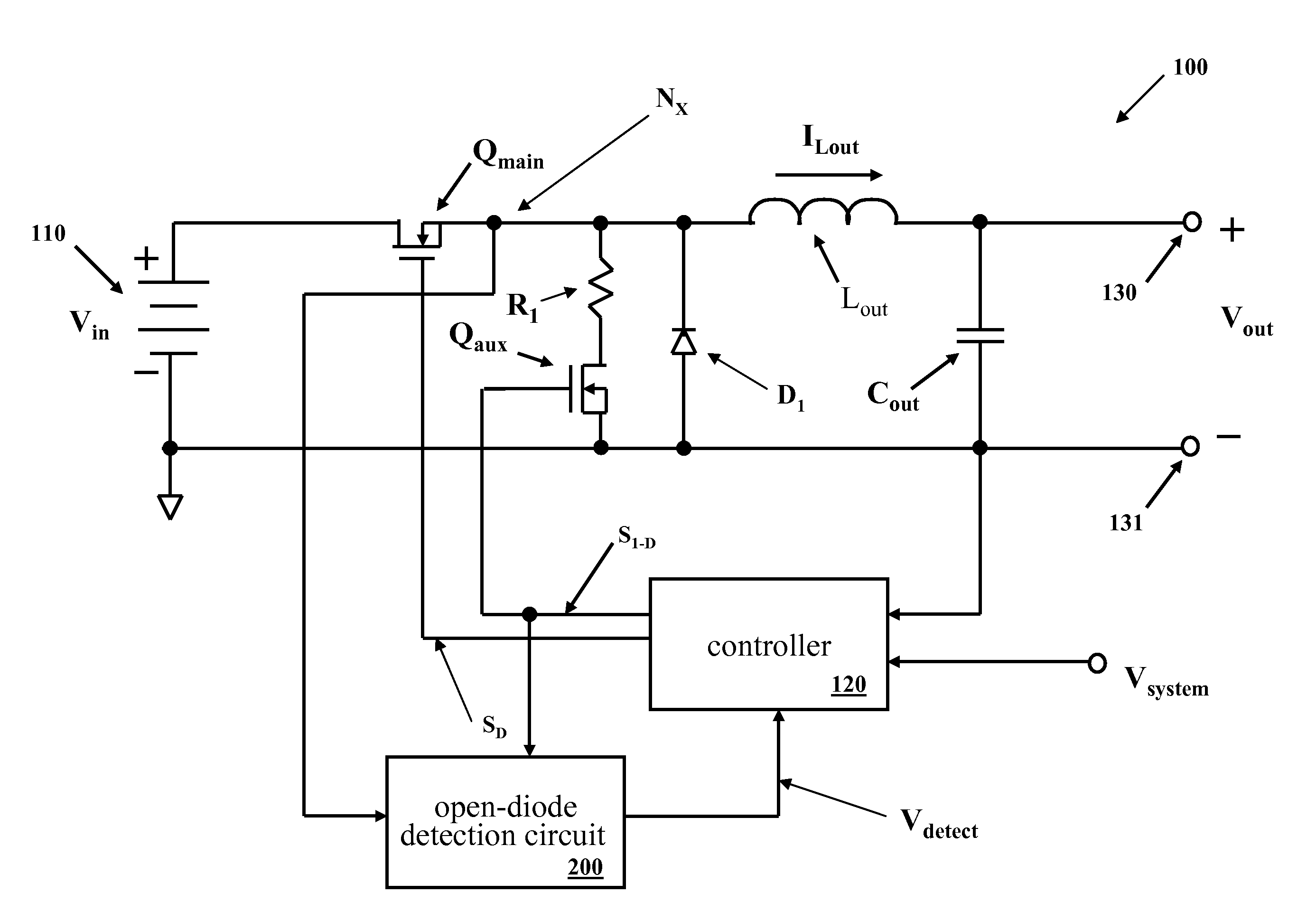
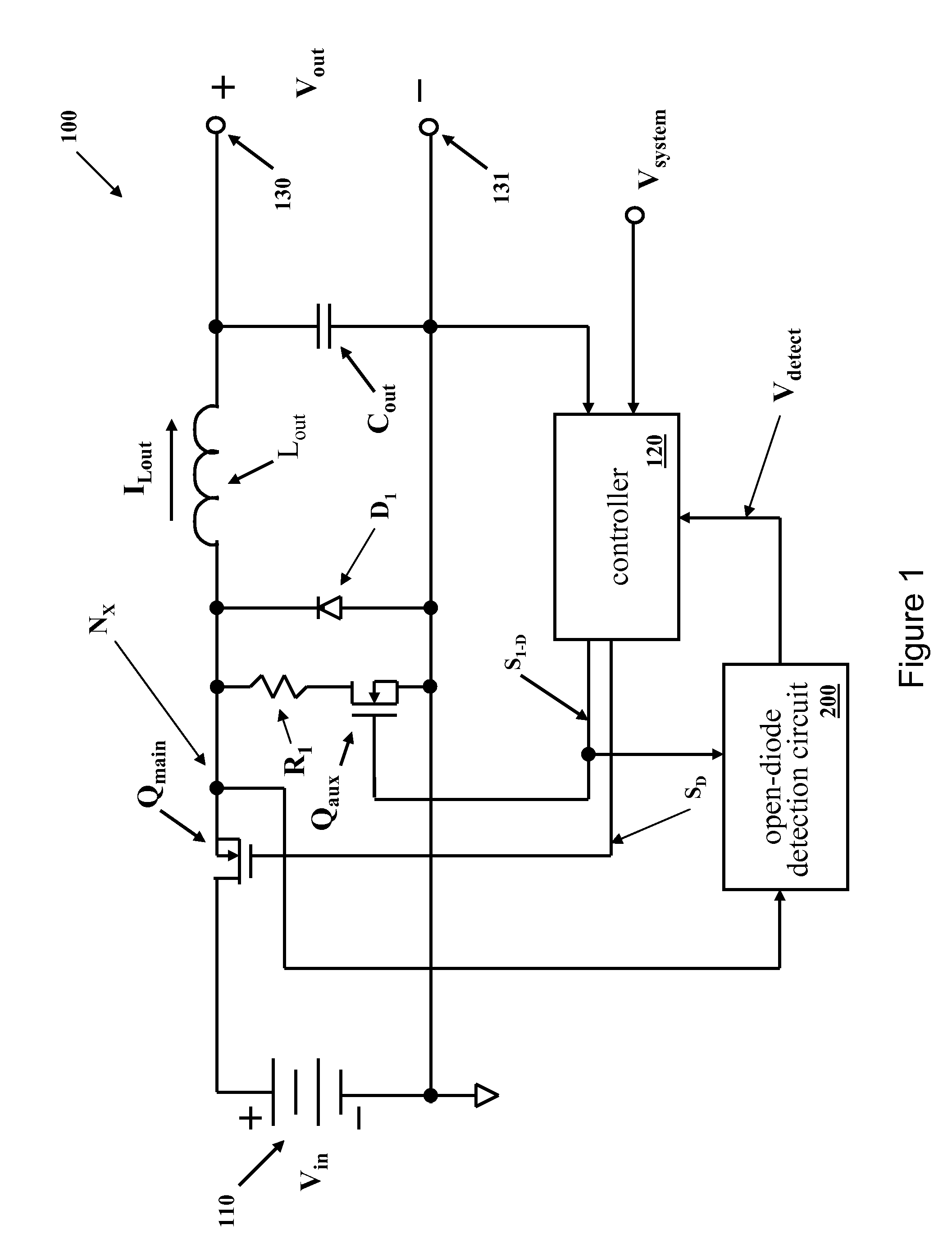
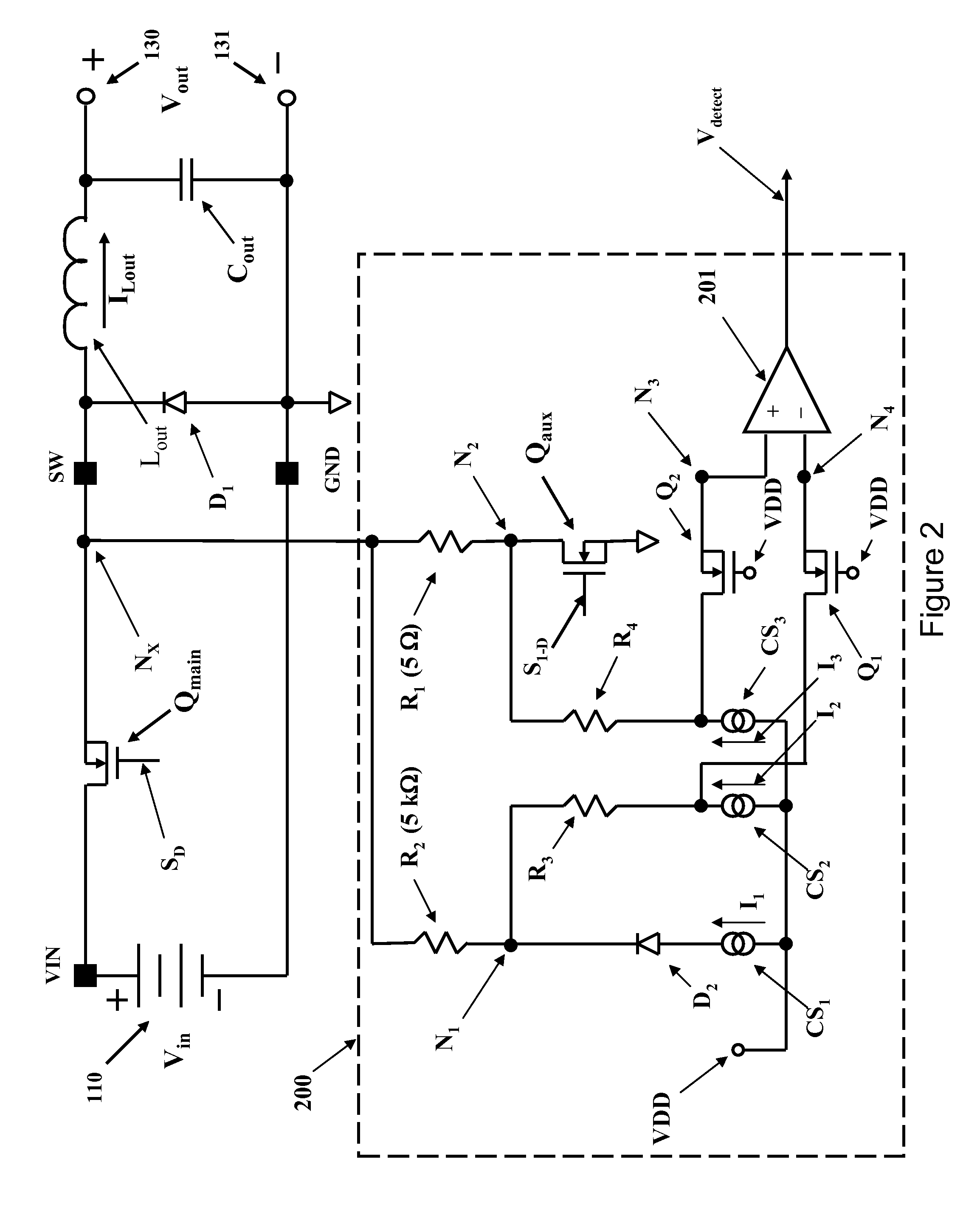
[0015]The present invention will be described with respect to exemplary embodiments in a specific context, namely a switch-mode power converter including an integrated circuit that provides a switching and control function, and a power diode coupled to and separated from the integrated circuit. The integrated circuit includes a process to detect an open-circuit condition in the portion of the circuit that includes the power diode.

[0016]An embodiment of the invention may be applied to various electronic power conversion devices, for example, to a power converter to produce a r...


PUM


Abstract

An embodiment of the invention relates to a switch-mode power converter including an inductor and an external rectifying diode. A series arrangement of a resistor and a switch are coupled in parallel with the external rectifying diode. The resistor and the switch enable continuous conduction mode, even at substantially no output current. A comparator senses a current level in the resistor. When the current level crosses a threshold level, the power converter is shut down. The current level is sensed with a second resistor coupled to a current source to produce a current sensing arrangement dependent on a ratio of resistances. Advantageously, the current level is sensed with clamp circuits coupled to the comparator, each clamp circuit including a series circuit arrangement of a field-effect transistor with a gate coupled to a voltage source.

Description

TECHNICAL FIELD[0001]An embodiment of the invention relates generally to electronic power conversion and methods, and more particularly to protecting a power converter against a circuit failure.BACKGROUND[0002]A switch-mode power converter (also referred to as a “power converter” or “regulator”) is a power supply or power processing circuit that converts an input voltage waveform into a specified output voltage waveform. DC-DC power converters convert a dc input voltage into a dc output voltage. Controllers associated with the power converters manage an operation thereof by controlling the conduction periods of switches employed therein. Generally, the controllers are coupled between an input and output of the power converter in a feedback loop configuration (also referred to as a “control loop” or “closed control loop”).[0003]Typically, the controller measures an output characteristic (e.g., an output voltage, an output current, or a combination of an output voltage and an output c...

Claims


Application Information

Patent Timeline
IPC IPC(8): H02H7/10G05F1/618
CPCY02B70/1466H02M3/1588Y02B70/10
Inventor TRESCASES, OLIVIERBERNARDON, DEREK
Owner INFINEON TECH AG
Why Eureka
Try Eureka