Systems and methods for controlling a pulsed laser by combining laser signals

a pulsed laser and laser signal technology, applied in the field of lasers, can solve the problems of high power pulse picker efficiency, instability of the cpa system, and additional system complexity

Inactive Publication Date: 2010-02-18
COHERENT INC
View PDF103 Cites 41 Cited by
  • Summary
  • Abstract
  • Description
  • Claims
  • Application Information

AI Technical Summary

Problems solved by technology

In addition to additional system complexity, the high power pulse picker may have other disadvantages.
The high power pulse picker may have low efficiency, which may typically be less than 80%.
The high power pulse picker may cause instability of the CPA system 100 and spatial distortions of an output optical beam.
The high power pulse picker including its radio-frequency (RF) electronics and power supply may also be bulky and require a significant amount of space relative to the rest of the CPA system 100.
Furthermore, the high power pulse picker may create additional heat due to its RF electronics and load.
Accurately directing individually triggered output pulses to a target may be difficult because an exact point of impingement of an output pulse on the target may not be known until after the output pulse impinges on the target.

Method used


Image

  • Systems and methods for controlling a pulsed laser by combining laser signals
  • Systems and methods for controlling a pulsed laser by combining laser signals
  • Systems and methods for controlling a pulsed laser by combining laser signals

Examples


Embodiment Construction

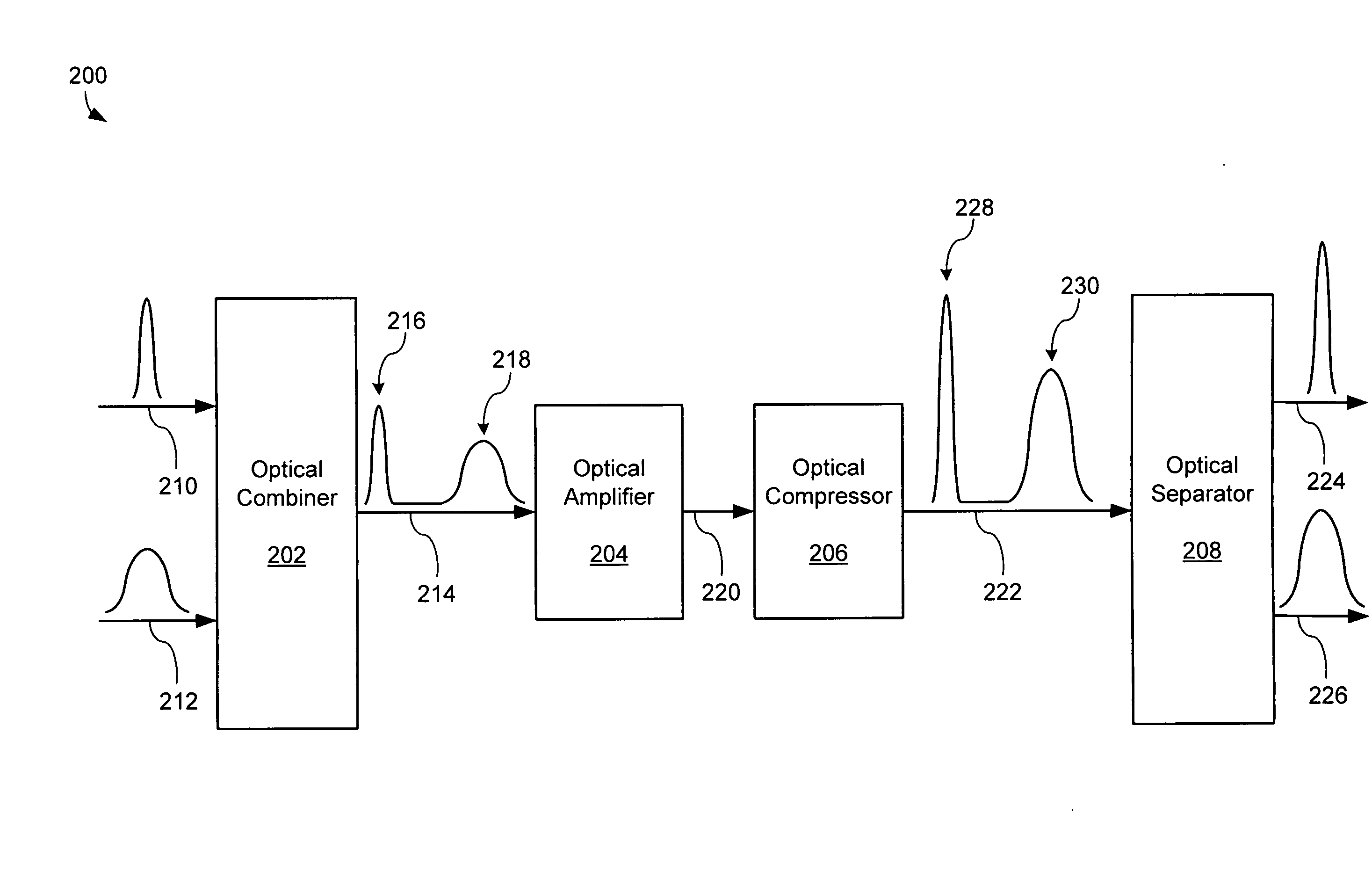
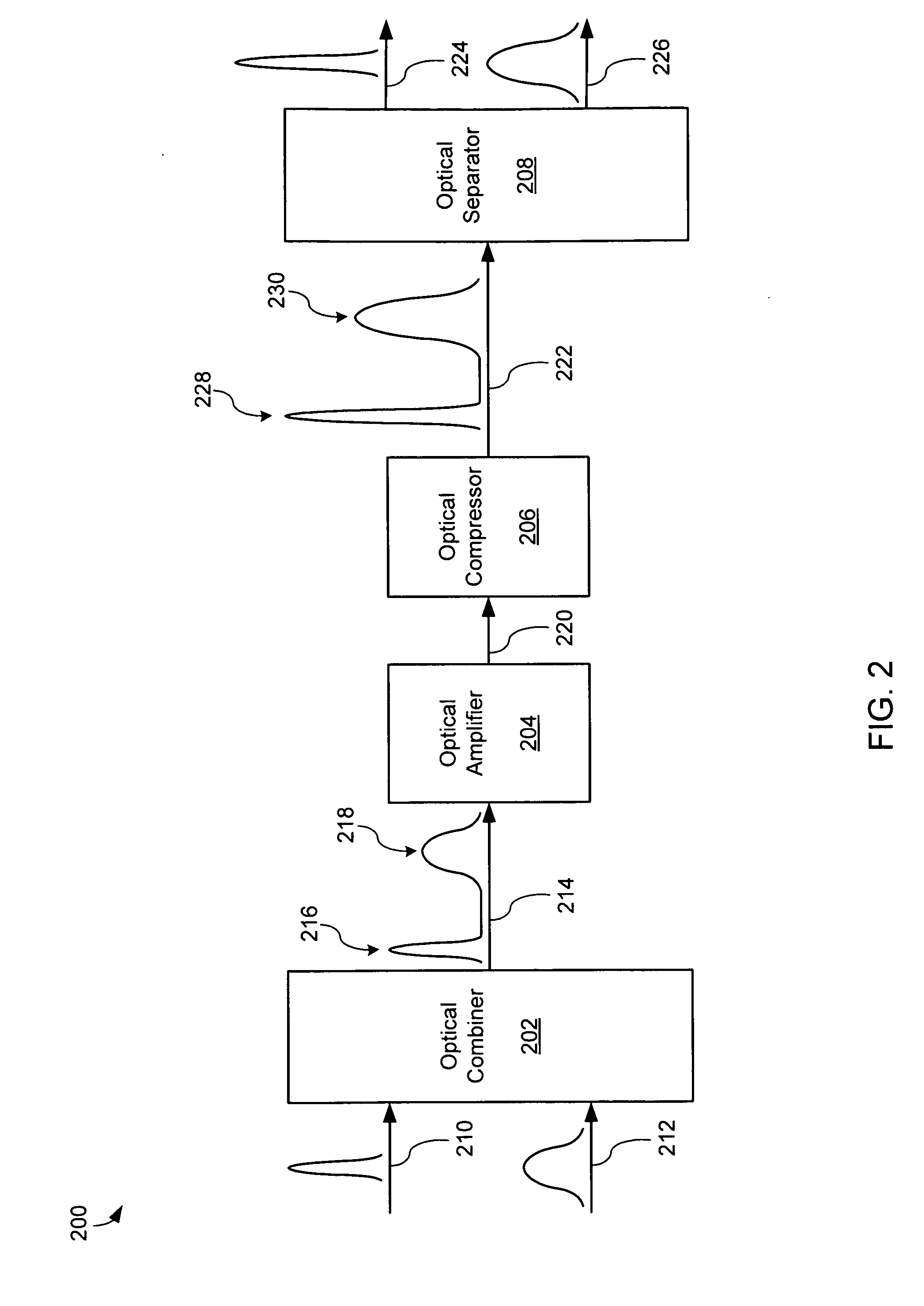
[0025]FIG. 2 is a block diagram of an exemplary multiplexed CPA system 200. The multiplexed CPA system 200 comprises an optical combiner 202, an optical amplifier 204, an optical compressor 206, and an optical separator 208. The optical combiner 202 may be configured to combine a primary optical signal 210 and a secondary optical signal 212 into a combined optical signal 214. The optical combiner 202 may include an optical multiplexer, a star coupler, a polarization combiner, coupled optical fibers, optical lenses, or other components configured to spatially combine the primary optical signal 210 and the secondary optical signal 212 into the combined optical signal 214. The combined optical signal 214 may include both a primary optical signal representation 216 and a secondary optical signal representation 218, which may co-propagate within a single optical medium such as an optical waveguide, optical fiber, and / or free space. The combined optical signal 214 may be separable accordi...


PUM


Abstract

An ultra-short pulsed laser system comprises an optical combiner, optical amplifier, optical pulse compressor, and optical separator. The optical combiner is configured to combine a primary optical pulse with a secondary optical signal to generate a combined optical signal. The primary optical pulse and the secondary optical signal have a distinguishable characteristic. The optical amplifier is configured to optically amplify the combined optical signal. The optical pulse compressor is configured to compress at least the primary optical pulse contained within the optically amplified combined optical signal and output a compressed combined optical signal. The optical separator is configured to separate the compressed combined optical signal into an output primary optical pulse and an output secondary optical signal according to the distinguishable characteristic.

Description

BACKGROUND[0001]1. Field of the Invention[0002]The present invention relates generally to the field of lasers, and more specifically to controlling a pulsed laser.[0003]2. Related Art[0004]Chirped Pulse Amplification (CPA) is very useful for producing ultra-short duration high-intensity pulses for use in high peak power ultra-short pulse laser systems using an optical amplifier. CPA increases the energy of an ultra-short laser pulse while avoiding optical amplifier damage and excessive nonlinear distortion. In this technique, the duration of the pulse is increased by first dispersing the ultra-short laser pulse temporally as a function of wavelength (a process called “chirping”) to produce a chirped pulse, then amplifying the chirped pulse, and then recompressing the chirped pulse to significantly shorten its duration. Stretching the pulse or lengthening the pulse in time reduces the peak power of the pulse and, thus, allows energy to be added to the pulse without incurring excessiv...

Claims


Application Information

Patent Timeline
Patent Type & Authority Applications(United States)
IPC IPC(8): H01S3/10
CPCH01S3/0057H01S3/06754H01S3/10046H01S2301/02H01S3/1302H01S3/2308H01S3/2383H01S3/10061
Inventor MIELKE, MICHAEL M.WAARTS, ROBERT G.TONG, SHACHANG, KOK WAI
Owner COHERENT INC
Why Eureka
Try Eureka