Wireless temperature sensor

a temperature sensor and wireless technology, applied in the field of integrated temperature sensors, can solve the problems of difficulty in adapting the core (rc) according to the desired temperature variation range, and achieve the effect of low cost and easy operation

Active Publication Date: 2010-02-18
INCIDE
View PDF27 Cites 11 Cited by
  • Summary
  • Abstract
  • Description
  • Claims
  • Application Information

AI Technical Summary

Benefits of technology

[0007]The present invention solves the aforementioned problems by means of an integrated temperature sensor with a low cost and consumption valid for the mentioned types of applications (RFID sensors or, more generally, wireless sensors). The sensor of the present invention comprises an oscillator generating a signal the frequency of which depends on the temperature, in which the dependence is achieved through the delay caused by a chain of a certain number of logic gates. A simple adaptation to the desired temperature variation range, which can be easily carried out by the direct scaling of the logic gates (since the total surface area is virtually invariable) against the total redesign required by the same action for sensors based on RC tanks, is thus achieved.
[0008]In one aspect of the present invention, an integrated temperature sensor with a low cost and consumption valid for an active, semiactive or passive RFID transponder is provided.

Problems solved by technology

However, the temperature sensor described in US 2005 / 0135456 A1 has a series of drawbacks, such as the need for a large amount of surface area to integrate the RC (resistor and capacitor) resonant tank, as well as the difficulty of adapting this core (RC) according to the desired temperature variation range.

Method used


Image

  • Wireless temperature sensor
  • Wireless temperature sensor
  • Wireless temperature sensor

Examples


Embodiment Construction

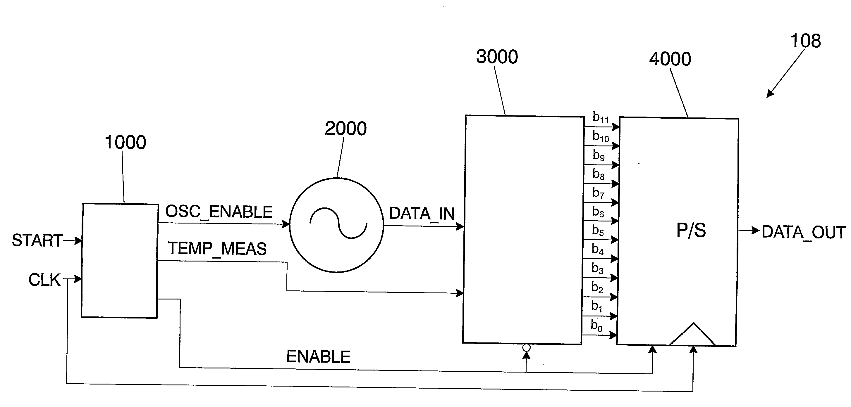
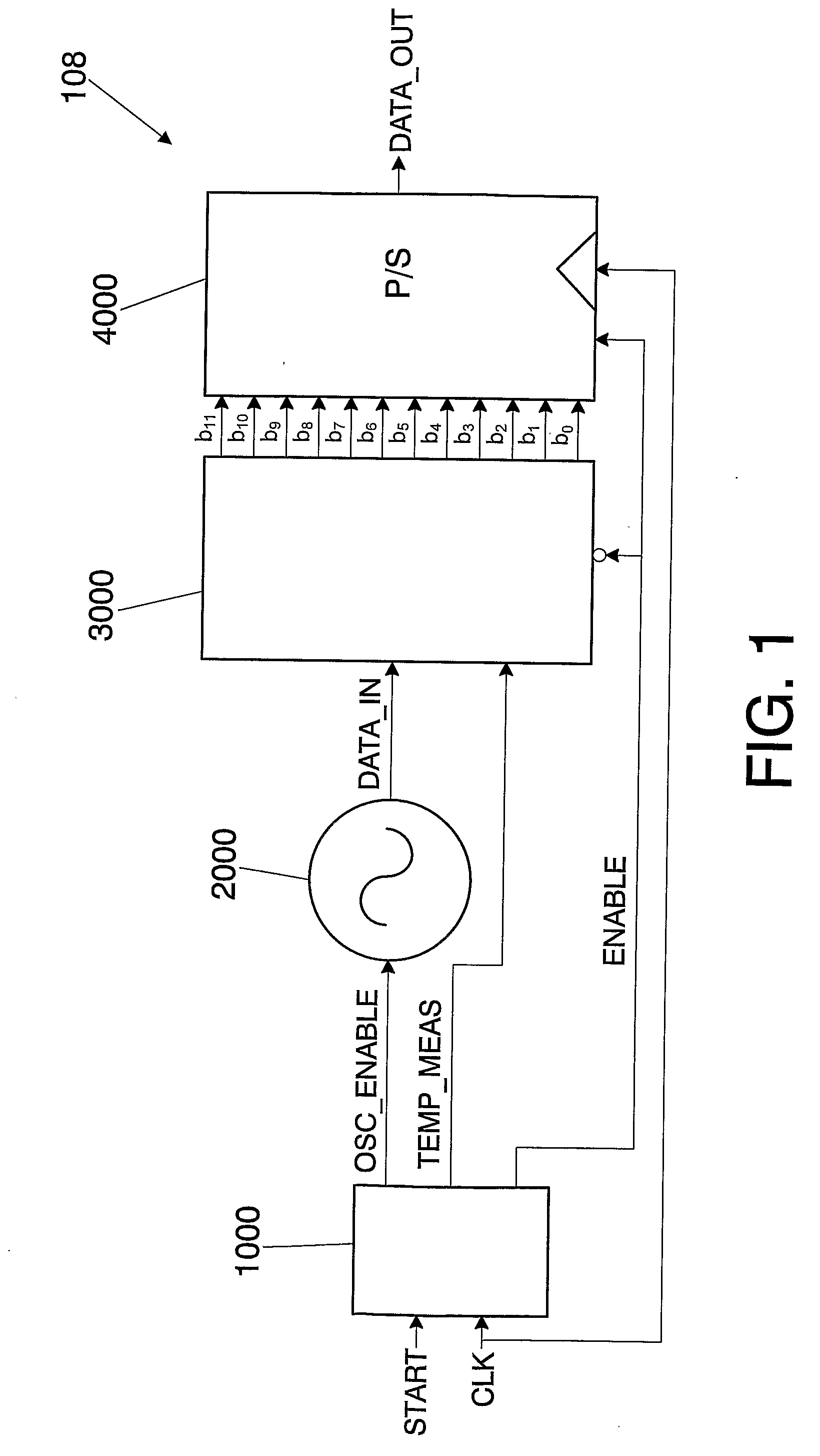
[0041]FIG. 1 depicts the block diagram of the temperature sensor 108 according to one embodiment of the present invention. The temperature sensor 108 of FIG. 1 can be implemented in a RFID (radio frequency identification) transponder or in any other wireless transponder in general.

[0042]The sensor 108 of FIG. 1 comprises an oscillator 2000, a binary counter 3000 and means for generating a serial digital signal 4000. The sensor 108 preferably further comprises control means 1000.

[0043]FIG. 1 shows the control means by means of a control logic block 1000, a temperature-dependent oscillator 2000, a binary counter 3000 and a parallel-to-serial converter 4000. In this embodiment of the present invention, the inputs to the sensor 108 are START and CLK. The first one (START) is a step signal used to initiate the measurement process of the sensor 108. Specifically, the start-up of the sensor 108 occurs with the rising flank of the signal “START”. The second one is the clock signal (CLK) use...


PUM


Abstract

The invention relates to an integrated temperature sensor (1) comprising: means (2000) for generating a pulse train (DATA_IN) at an oscillation frequency, means (3000) for counting the number of pulses during a fixed period of time independent of a temperature to be measured (T) and for generating a plurality of bits (b11, b10, . . . , b0) indicating the number of pulses in the pulse train (DATA_IN), and means (4000) for generating a serial digital signal (DATA_OUT) from said bits (b11, b10, . . . , b0), in which the means (2000) for generating a pulse train (DATA_IN) include a plurality of logic gates (2410, 2420, 2430, 2440, 2450) which can introduce a delay dependent on the temperature to be measured (T), said means (2000) generating a pulse train (DATA_IN) the oscillation frequency of which is dependent on said temperature to be measured (T). The invention also relates to a temperature measurement method and to a transponder for a wireless system.

Description

FIELD OF THE INVENTION[0001]The present invention relates to the field of integrated temperature sensors, and more specifically, to those with a low cost and consumption, as well as to the field of wireless transponders incorporating the sensors.BACKGROUND OF THE INVENTION[0002]Integrated circuits with a minimalist design in relation to the power consumption thereof are known. The origin of this trend is the extensive growth of those applications in which energy consumption is crucial, such as RFID (Radio Frequency Identification) transponders, wireless sensors, etc.[0003]Most of these circuits have a battery with a very limited energy capacity (active circuits) and the rest of the circuits collect and temporarily store the energy from a radiant source for the correct operation thereof (passive circuits).[0004]Therefore in both of the circuits it is desirable to have low power consumption.[0005]Patent application US 2005 / 0135456 A1 describes a radio frequency temperature sensor comp...

Claims


Application Information

Patent Timeline
IPC IPC(8): G01K1/02G01K15/00G08C19/12
CPCG01K1/024G01K7/346G01K7/32
Inventor UBARRETXENA BELANDIA, ARITZBERENGUER-PEREZ, ROCANTON, CESAR MATINEZEGURROLA LOPEZ, DANIELHERNANDEZ DE MIGUEL, JAVIER
Owner INCIDE
Why Eureka
Try Eureka