Method and apparatus for reducing cost of an optical amplification in a network

Active Publication Date: 2010-02-18
TELLABS OPERATIONS
View PDF40 Cites 21 Cited by
  • Summary
  • Abstract
  • Description
  • Claims
  • Application Information

AI Technical Summary

Benefits of technology

[0008]A method or corresponding apparatus in an example embodiment of the present invention provides a procedure to plan a deployment of optical network elements (ONEs), such as optical amplifiers, in an optical network. An example embodiment of the procedure initializes models of ONEs within a topology of ONEs, where models of amplifiers include amplification and noise characteristics compatible with respective ONEs. After initialization, an optical signal-to-noise ratio (OSNR) margin table is computed as a function of the topology and the model

Problems solved by technology

Deploying optical network elements (ONEs) to form an optical network is a difficult and expensive proposition: network providers need to correctly anticipate customer demand while building reliable networks as inexpensively as possible.
Lower BERs are better; ideal (i.e., noise-free) receivers operate with BERs of zero (0), but shot noise and thermal noise at real receivers cause bit detection errors, raising BERs to measurable levels.
Eventually, increasing the bit rate depresses the OSNR too far, pushing the BER above acceptable levels.
As light propagates through a network, however, it is absorbed and scattered, reducing the signal power and the OSNR.
In addition, signals propagating through optical fiber suffer from loss due to four-wave mixing, chromatic dispersion, and polarization mode dispersion, further reducing the OSNR.
This process, known as optical regeneration, or simply regeneration, boosts the OSNR but requires relatively expensive transponders.
Unfortunately, the transponder complexity and cost increase with the data rate and the number of channels, making regeneration an unattractive option for maintaining OSNR in metro WDM networks.

Method used


Image

  • Method and apparatus for reducing cost of an optical amplification in a network
  • Method and apparatus for reducing cost of an optical amplification in a network
  • Method and apparatus for reducing cost of an optical amplification in a network

Examples


Embodiment Construction

[0019]A description of example embodiments of the invention follows.

[0020]Example embodiments of the present invention provide a method or apparatus for planning deployment of optical network elements (ONEs) in metropolitan wavelength-division multiplexing (WDM) networks.

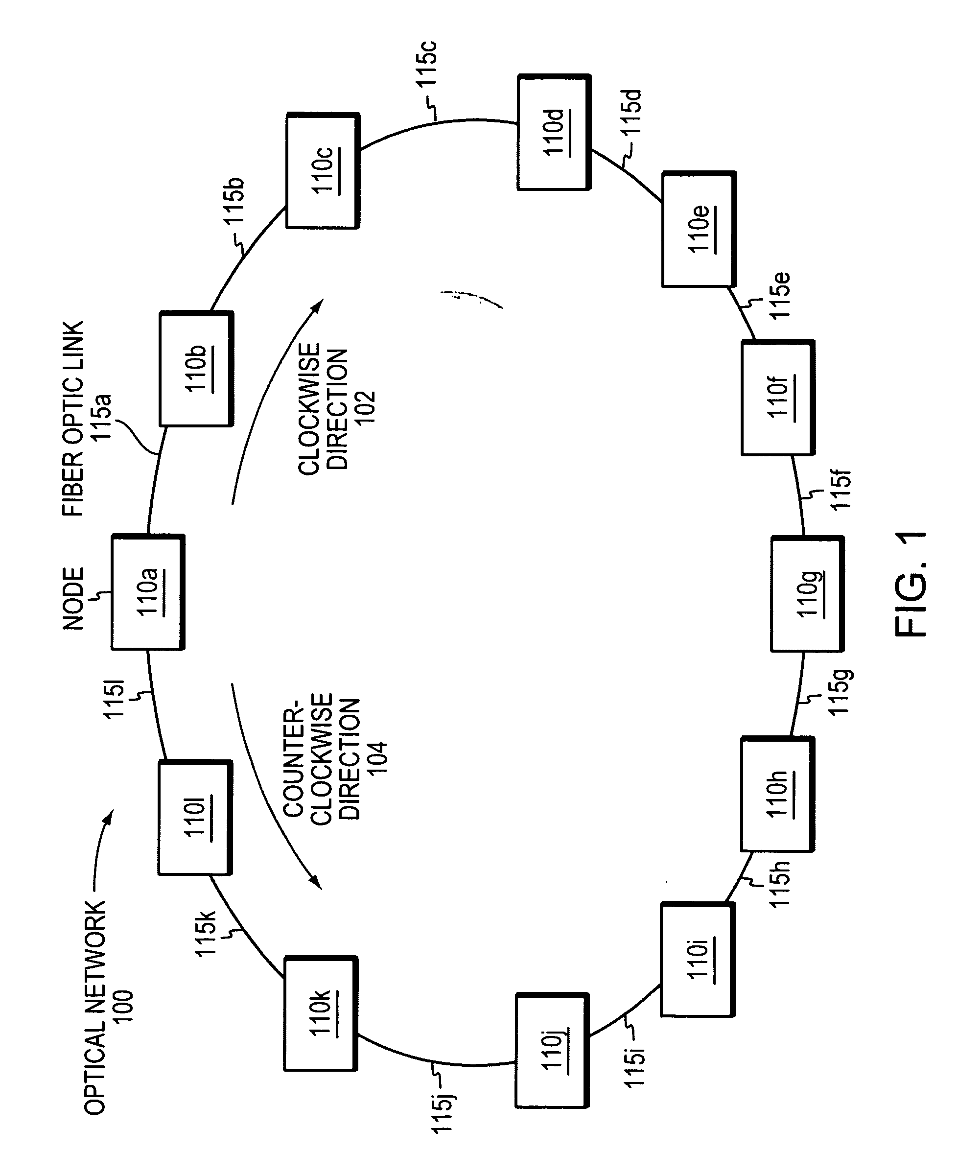
[0021]FIG. 1 is a block diagram that illustrates an optical network 100 including a plurality of nodes 110a-l connected via a plurality of fiber optic links 115a-l. For example, node 115a connects to node 115b via a first fiber optic link 115a in a clockwise direction 102. In a counterclockwise direction 104, node 115a connects to node 115l via a second fiber optic link 115l. Typically, nodes include central offices, communications sites, communications devices, etc. The optical network 100 shown in FIG. 1 has a ring topology, whereas other optical networks may have other topologies including linear, mesh, unidirectional, bidirectional, or hybrid topologies. In addition, optical networks may have any number of nodes...


PUM


Abstract

Signals propagating in wavelength division multiplexing (WDM) optical networks suffer from loss, which decreases optical signal-to-noise ratios (OSNRs) and degrades a quality of received transmissions. Present methods of boosting OSNRs involve regeneration using transponders, which scale in complexity with the number of WDM channels. Optical amplifiers may boost signal strength, but amplified spontaneous emission (ASE) noise often reduces OSNR despite increases in signal strength, although changing the amplifier operating settings may reduce emitted ASE noise power. A method or corresponding apparatus in an example embodiment of the present invention provides a planning tool for deploying optical amplifiers in an optical network in a manner that reduces the need for optical regeneration, reducing cost and complexity of the deployed network. In one embodiment, the disclosed planning tool may substitute models of high-gain amplifiers operating at low settings for models of low-gain amplifiers operating at high settings.

Description

RELATED APPLICATIONS[0001]This application is related to U.S. application Ser. No. 11 / 354,705, filed on Feb. 14, 2006; and Attorney Docket Nos. 2376.2253-000, entitled “Method and Apparatus for Designing Any-To-Any Optical-Signal-to-Noise Ratio in Optical Networks;” 2376.2255-000, entitled “Method and Apparatus for Displaying and Identifying Available Wavelength Paths Across a Network;” and 2376.2263-000, entitled “Method and Apparatus for Simplifying Planning and Tracking of Multiple Installation Configurations;” each of which is being filed concurrently. The entire teachings of the above applications are incorporated herein by reference.BACKGROUND OF THE INVENTION[0002]Deploying optical network elements (ONEs) to form an optical network is a difficult and expensive proposition: network providers need to correctly anticipate customer demand while building reliable networks as inexpensively as possible. In addition, network providers must also anticipate future technological develop...

Claims


Application Information

Patent Timeline
IPC IPC(8): H04B10/08
CPCH04B10/275H04B10/27
Inventor JENKINS, DAVID W.ANAND, RAMASUBRAMANIANAYALA, HECTORLARIKOVA, JULIA Y.FISHER, KENNETH M.
Owner TELLABS OPERATIONS
Why Eureka
Try Eureka