
Physiological monitoring garment

a monitoring garment and garment technology, applied in the field of wearable electronics, can solve the problems of unsightly and uncomfortable wires, not wearing well, and affecting the wear of people, and achieve the effect of simple manufacturing and no impeded mobility

Inactive Publication Date: 2010-02-18
TING JOSEPH +2
View PDF103 Cites 93 Cited by
  • Summary
  • Abstract
  • Description
  • Claims
  • Application Information

AI Technical Summary

Benefits of technology

The solution provides a comfortable, robust, and washable physiological monitoring garment with integrated sensors and a flexible data / power bus that maintains sensor functionality during movement and repeated washing, enhancing user convenience and mobility.

Problems solved by technology

The problem with this design is that the wires are separate from the textile material of the clothing.
As a result, the wires are unsightly and uncomfortable, do not wear well, can catch and tangle on objects, reduce mobility, add weight, are not washable, and are not resistant to corrosion.
In general, such a design is not very robust.
But, since the metallic yarn only runs in one direction, communications and interconnections between the electronic devices can only take place in that direction.
This design thus raises serious design concerns, namely manufacturability, shielding, and electrical interference.
Moreover, the fabric including the soldered-on electronic components is delicate, cannot be washed, has no stretch, and is uncomfortable to wear.
Finally, if the fabric is folded back on itself, an electrical short will occur.
Thus, special insulative coatings or substrates must be used which further render the fabric uncomfortable to wear.
Still, routing of the data or power between the devices is limited without extensive formation of electrical junctions in the fabric—a very cumbersome manufacturing process.
In addition, such garments are also uncomfortable and cannot withstand repeated wash cycles.
To date, however, the applicants are unaware of a marketable system which employs low profile sensors held in position against the body throughout a typical range of movements for mechanical and electrical coupling.
And, although the prior art teaches garments with integral electrodes and sensors, there is a general failure in the art to consider a non-intrusive, conformable, comfortable integrated data / power bus for providing power to the sensors and electrodes (as required) and for routing sensor / electrode signals to the appropriate processing and / or transmission circuitry.
A review of the prior art reveals no system which meets the above criteria for a viable physiological monitoring garment.

Method used


Image

  • Physiological monitoring garment
  • Physiological monitoring garment
  • Physiological monitoring garment

Examples


Embodiment Construction

[0067]Aside from the preferred embodiment or embodiments disclosed below, this invention is capable of other embodiments and of being practiced or being carried out in various ways. Thus, it is to be understood that the invention is not limited in its application to the details of construction and the arrangements of components set forth in the following description or illustrated in the drawings. If only one embodiment is described herein, the claims hereof are not to be limited to that embodiment. Moreover, the claims hereof are not to be read restrictively unless there is clear and convincing evidence manifesting a certain exclusion, restriction, or disclaimer.

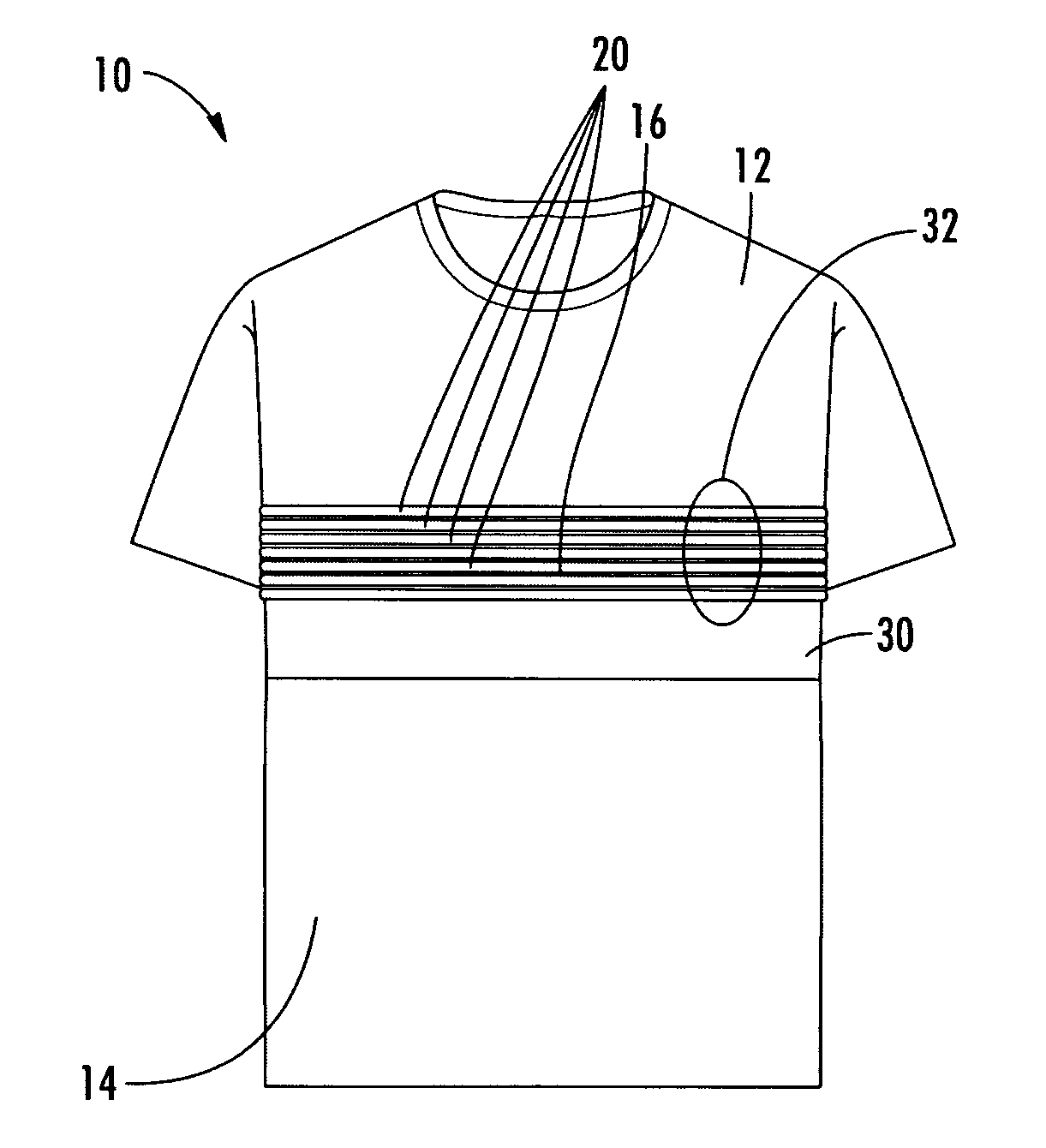
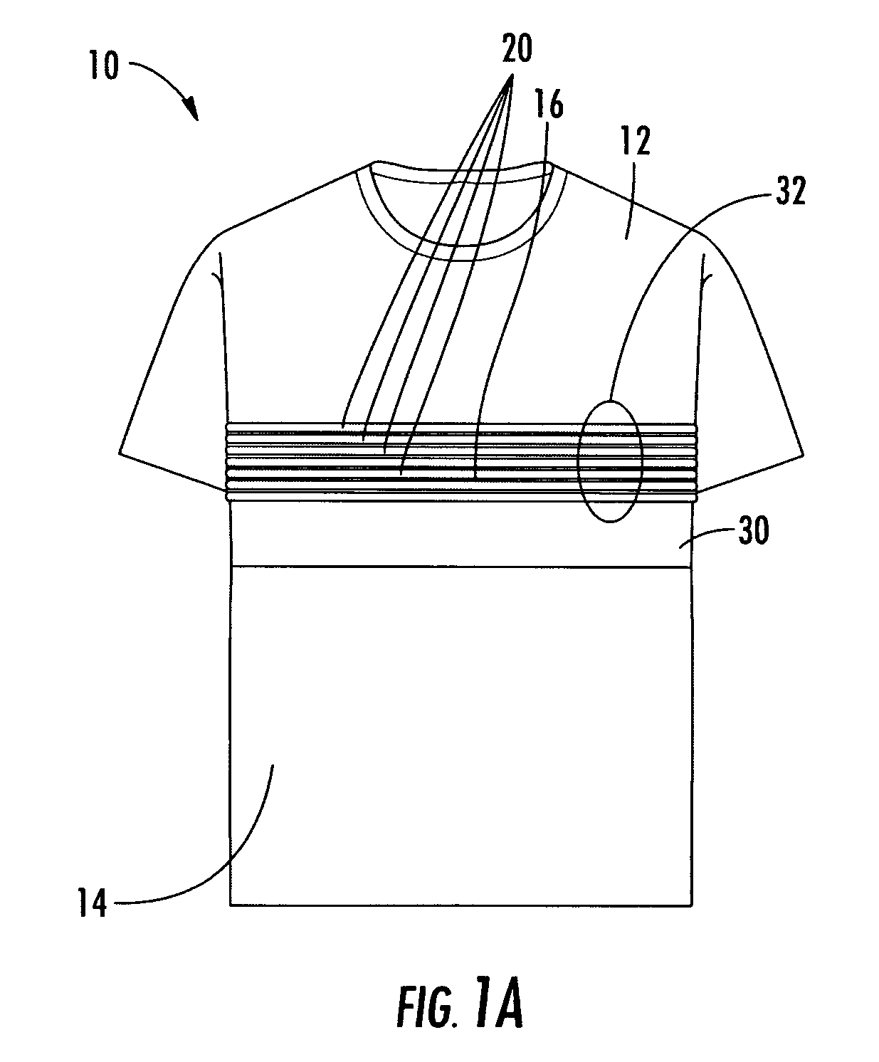
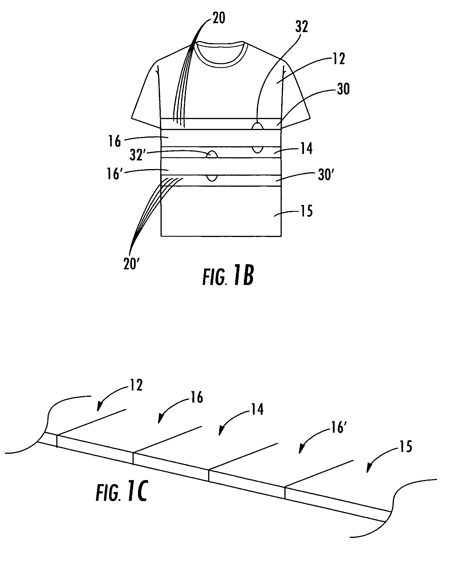
[0068]One embodiment of a physiological monitoring garment in accordance with the present invention is shown at 10 in FIG. 1A. As shown, physiological monitoring garment 10 includes elastic fabric portions 12 and 14. Elongate stretchable textile data / power bus 16 is disposed between elastic fabric portions 12 and 14. Elonga...


PUM


Abstract

A physiological monitoring garment includes a fabric portion. At least one elongate stretchable textile data / power bus is disposed the fabric portion. The elongate stretchable textile data / power bus includes a plurality of integral conductors, woven, knitted, or braided along the length thereof. One or more sensors are connected to the elongate stretchable textile data / power bus.

Description

RELATED APPLICATIONS[0001]This application is a continuation of prior U.S. patent application Ser. No. 10 / 922,336 filed Aug. 20, 2004 which claims the benefit of and priority to U.S. Provisional Patent Application Ser. No. 60 / 497,423 filed Aug. 22, 2003, and each application is incorporated herein by reference.GOVERNMENT RIGHTS[0002]This invention was made with U.S. Government support under Contract No. Contract No. DAMD17-03-C-0022 awarded by the U.S. Army Medical Material Command. The Government may have certain rights in the subject invention.FIELD OF THE INVENTION[0003]This invention relates to “wearable electronics”, “wearable computers”, “smart fabrics” and the like and more particularly a physiological monitoring garment including at least an integrated data / power bus. This invention also relates to a respiration monitoring device and sensors useful in connection with the physiological monitoring garment or other physiological sensor systems.BACKGROUND OF THE INVENTION[0004]T...

Claims


Application Information

Patent Timeline
Patent Type & Authority Applications(United States)
IPC IPC(8): A61B5/04A61B5/00A41D1/00A41D13/12A61B5/08A61B5/11A61B5/296
CPCA41D1/002A41D13/1281A61B5/01A61B5/0402A61B5/0408A61B5/6831A61B5/0488A61B5/0492A61B5/0816A61B5/11A61B5/6804A61B5/0478G16H40/63A61B5/25A61B5/318A61B5/291A61B5/296A61B5/389A61B5/27
Inventor TING, JOSEPHFARRELL, BRIANBOWMAN, JEREMY
Owner TING JOSEPH
Learn More