Method for Detecting and/or Monitoring a Wound Using Infrared Thermal Imaging

Inactive Publication Date: 2010-02-18
OXYBAND TECH INC
View PDF7 Cites 53 Cited by
  • Summary
  • Abstract
  • Description
  • Claims
  • Application Information

AI Technical Summary

Benefits of technology

[0008]The problem stated above is that monitoring the healing status of a wound is desirable for aiding recovery, but many of the conventional means for wound detection such as thermal imaging are not adapted for monitoring ongoing wound recovery. The inventors therefore considered functional elements of a thermal imaging system, looking for elements that exhibit modularity that could potentially be harnessed to provide thermal imaging but in a manner that would not limit to detection but that would enhance comprehensive diagnostic and prognostic capabilities.
[0010]The present inventor realized in an inventive moment that if, at the point of imaging, multiple detectors could be employed from different angles significant dimensional improvement might result in thermal images rendered. The inventor subsequently realized also that the thermal progression of radiation released from a localized area of damaged tissue over time might be quantified to produce useful prognosis data covering different types of wound treatment therapies. The inventor therefore constructed a unique thermal imaging system for imaging damaged tissue such as in a wound that allowed tri-dimensional infrared modeling of a wound in one embodiment and ongoing prognosis of wound recovery determined from image analysis of multiple images rendered of the same wound over time. A significant improvement in diagnostic and prognostic capabilities results with no inconveniences or any residual side effects created.
[0020]In another aspect of the system, the damaged tissue is illuminated during thermal imaging to improve image contrast. In the embodiment using more than one imaging device the damaged tissue is also illuminated during thermal imaging to improve image contrast. In an aspect of the method, a step is added between steps (c) and (d) for illuminating the damaged tissue to improve image contrast.

Problems solved by technology

The problem stated above is that monitoring the healing status of a wound is desirable for aiding recovery, but many of the conventional means for wound detection such as thermal imaging are not adapted for monitoring ongoing wound recovery.

Method used


Image

  • Method for Detecting and/or Monitoring a Wound Using Infrared Thermal Imaging
  • Method for Detecting and/or Monitoring a Wound Using Infrared Thermal Imaging
  • Method for Detecting and/or Monitoring a Wound Using Infrared Thermal Imaging

Examples


Embodiment Construction

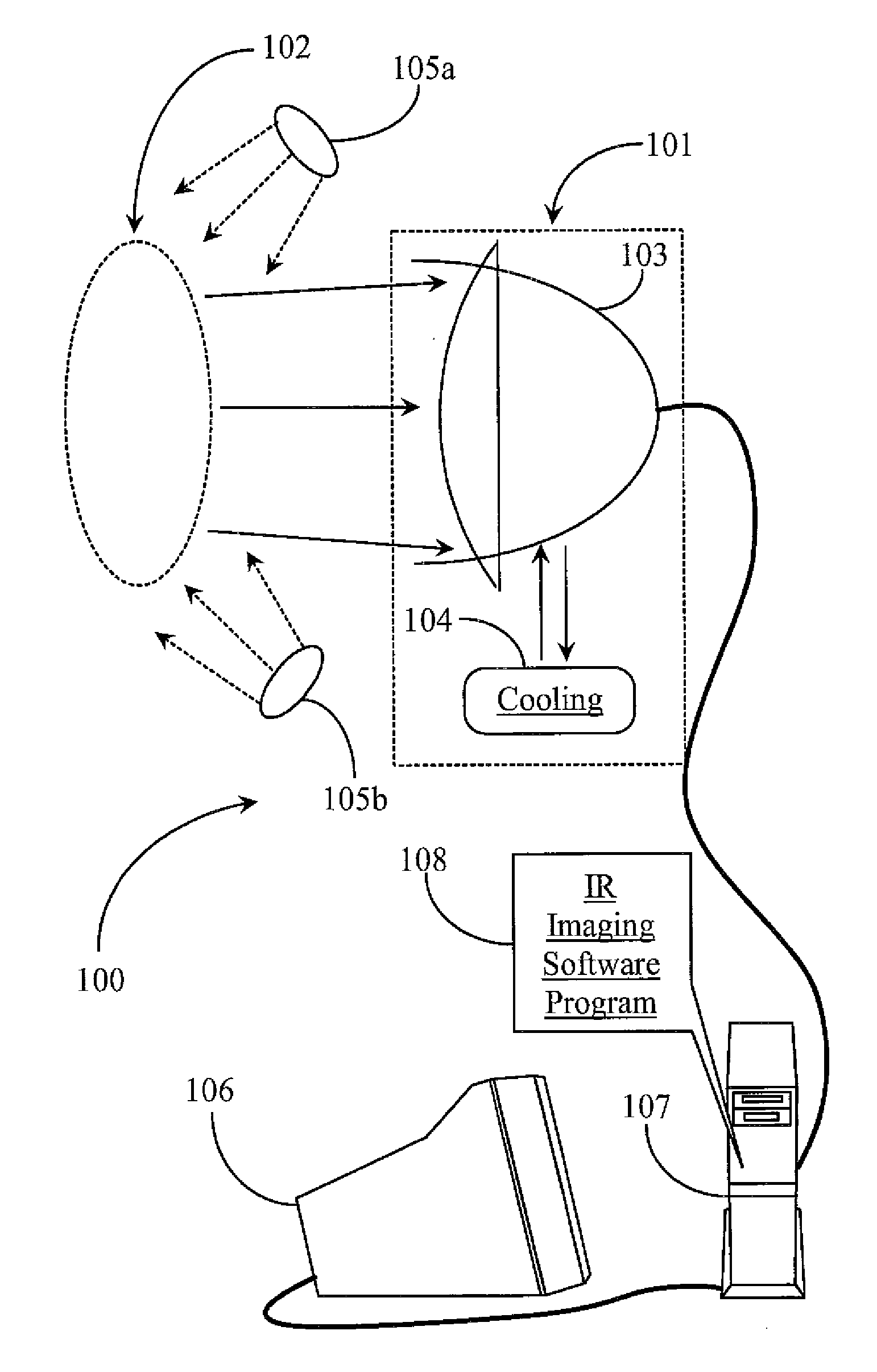
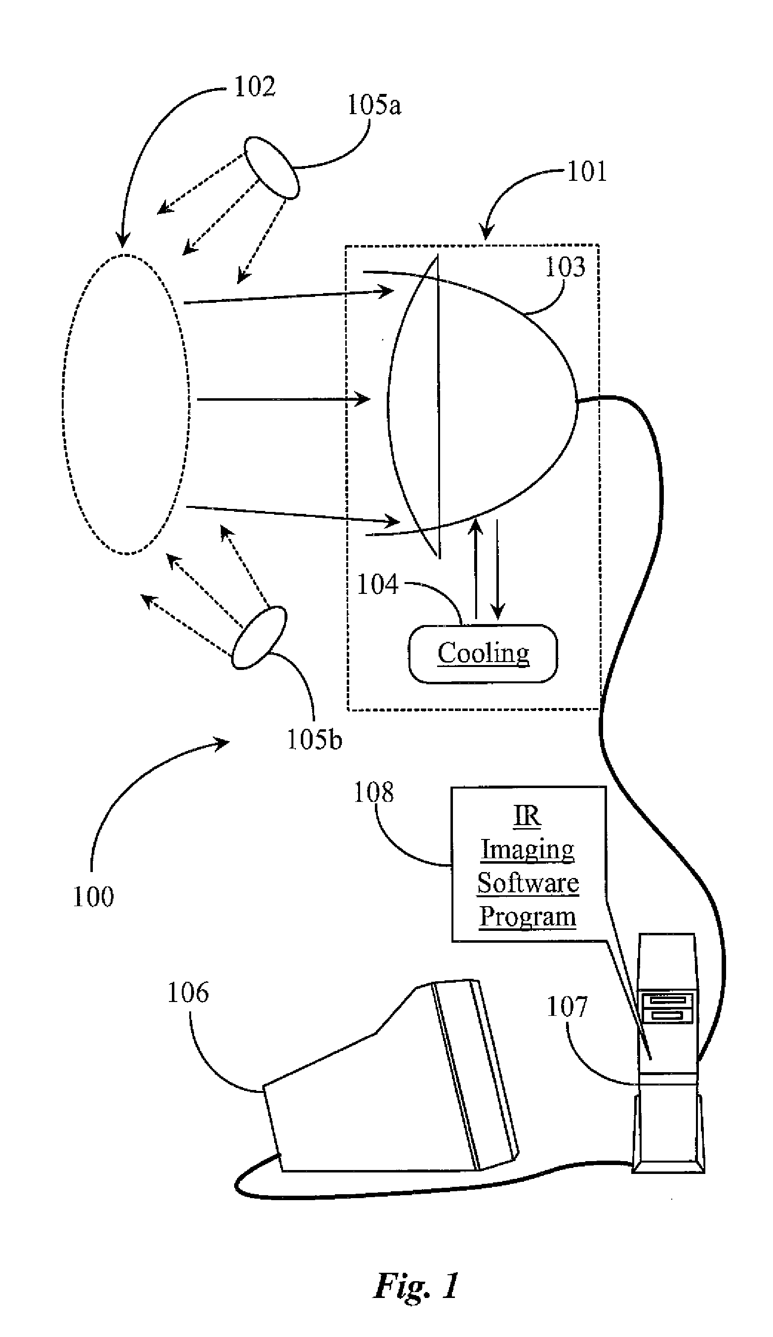
[0028]FIG. 1 is an architectural view of a digital thermal imaging system 100 according to an embodiment of the present invention. System 100 is adapted as a thermal medical imaging system that may be used to detect and monitor visible or non-visible wounds. The type of imaging performed may be classed as no-contact thermal imaging using an infrared heat detector unit 101, which may be an infrared camera or a digital camera also equipped with infrared sensors and a mode for thermal imaging. Thermal detection unit 101 may be referred to in this specification as an infrared camera 103 having a cooling cell 104.

[0029]In one embodiment of the present invention, camera 103 is cooled using some form of cooling mechanism 104. Mechanism or cell 104 may be a thermoelectric cooling cell, a forced air unit, or a cryogenic or water-filled unit. As described further above in the background section, cameras that are cooled tend to be the better resolution cameras. Cooling is not, however required...


PUM


Abstract

A system for diagnosing damaged tissue includes a thermal imaging device, a data processing device including a digital media generic to or associated there with connected to the thermal imaging device, an image display device connected to or integrated with the data processing device and a graphics user interface resident on the digital media of the data processing device and executable to display on the image display device, the interface enabling user configuration of various aspects of thermal imaging and data analysis functions.

Description

BACKGROUND OF THE INVENTION[0001]1. Field of the Invention[0002]The present invention is in the field of medical imaging systems and methods of use, and pertains more particularly to methods and apparatus for detecting and / or monitoring tissue wounds using thermal imaging.[0003]2. Discussion of the State of the Art[0004]In the art of medical imaging and at the time of this application, there are a variety of different technologies used in medical imaging. More recently, medical infrared imaging (MII) techniques such as digital infrared thermal imaging (DITI) have been used for early disease detection in specific medical diagnostic procedures such as detecting breast cancer. These techniques are broadly known in the medical field as Medical Thermography.[0005]A thermography image is a color image representing a thermal radiation pattern recorded from detecting thermal radiation local to the site of a lesion or growth. In general the concept involves measuring changes in thermal radia...

Claims


Application Information

Patent Timeline
IPC IPC(8): A61B6/00
CPCA61B5/015A61B5/0059
Inventor POSTEL, OLIVIER B.
Owner OXYBAND TECH INC
Why Eureka
Try Eureka