
Low air loss moisture control mattress overlay

a mattress and moisture control technology, applied in the field of mattresses or mattress coverlets, can solve the problems of skin death or atrophy, ulcers or sores, and patients that are bedridden or immobile can develop pressure sores or bedsores,

Inactive Publication Date: 2010-02-25
SPAN-AMERICA MEDICAL SYSTEMS
View PDF8 Cites 64 Cited by
  • Summary
  • Abstract
  • Description
  • Claims
  • Application Information

AI Technical Summary

Benefits of technology

The system effectively monitors and controls moisture levels, preventing skin maceration, maintaining patient comfort, and reducing the need for large compressors, while ensuring airflow under patient load and providing flexible treatment options, including static or alternating pressure support.

Problems solved by technology

Often, patients that are bedridden or immobile can develop decubitus ulcers (pressure sores or bedsores).
Continuous lack of blood flow, and the resultant lack of oxygen, can cause the skin to die or atrophy, and cause ulcers or sores to form.
Friction and shear of the skin against the support surface can lead to skin tears and decubitus ulcers.
Moisture and heat may lead to skin maceration.
Turning or repositioning of patients, however, is not always possible, particularly where trained medical staff is not available.
Additionally, repositioning can be painful and disruptive for the patient.
While each of these approaches is useful for its purpose, there are various disadvantages with these approaches and in particular, with using them individually.
Such large compressor pumps tend to be very noisy, require high electrical consumption, and generate significant heat in a relatively confined area.
Such high electrical consumption, and the additional need for continuous blower operation, has, in the past, resulted in potential over-heating of the air used to circulate about the patient.
Conversely, in the case of an elderly patient, airflow directly across their body could result in an uncomfortable reduction in body temperature or even a drying out of the skin beyond that which is helpful.
Additionally, having holes in air cells of an inflatable air system results in a support surface that will deflate if there is a loss of electrical power or if no such power supply is available.
Further, having perforations in the patient-bed contact surface results in a mattress that is not fluid-proof.
All three referenced approaches generally fail in some respects to allow air to flow under the load (i.e., underneath the patient) or through the top surface to the patient's skin when supporting the weight of the patient.
Similarly, some prior art mattresses and mattress coverlets have had difficulty in controlling billowing.
Billowing is generally the uncontrolled inflation of the upper surface of a mattress or mattress coverlet in the area immediately surrounding the outline of a patient's body when the patient lies on the mattress.
In essence, the mattress or mattress coverlet fails to fully support a patient and instead seemingly envelops them when the patient's weight is applied thereto.
Thus, such billowing further illustrates the failure of some prior mattresses and / or mattress coverlets to fully support the patient, therefore resulting in air flow through the mattress, mattress top layer, or through the coverlet (i.e., the three aforementioned approaches) and around the patient, rather than flowing underneath the patient to aid in controlling moisture and heat.
While various implementations of therapeutic mattresses or mattress coverlets have been developed, no design has emerged that generally encompasses all of the desired characteristics as hereafter presented in accordance with the subject technology.

Method used


Image

  • Low air loss moisture control mattress overlay
  • Low air loss moisture control mattress overlay
  • Low air loss moisture control mattress overlay

Examples


Embodiment Construction

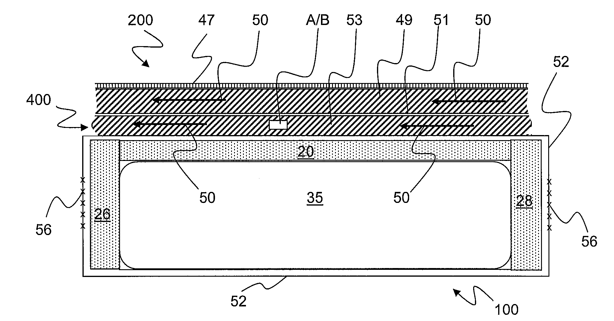
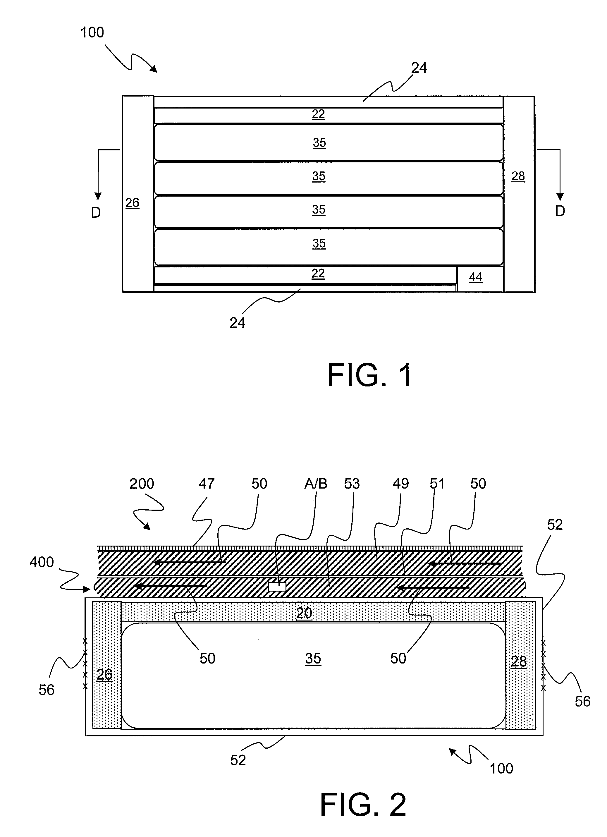
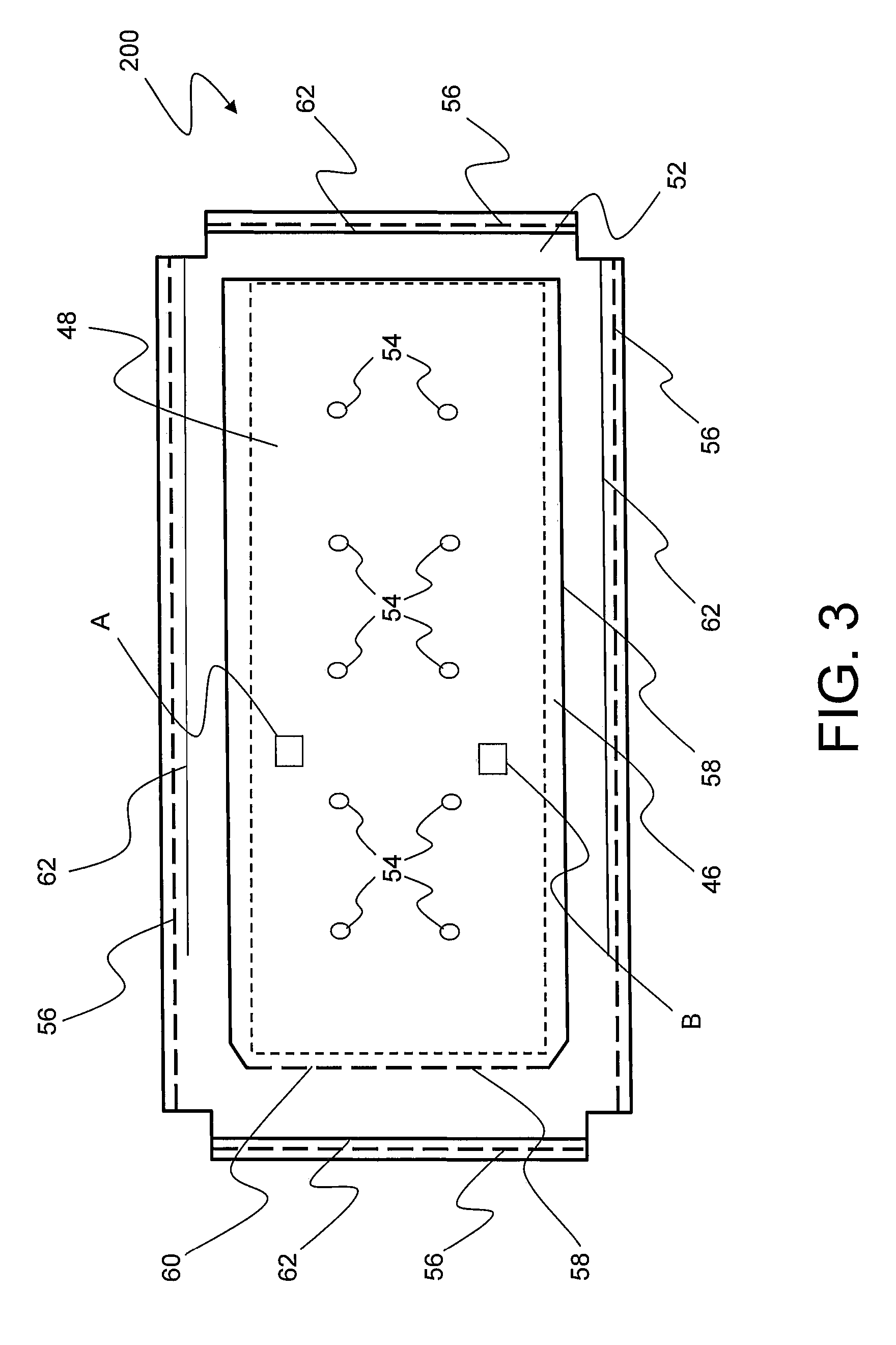
[0043]As discussed in the Summary of the Invention section, the present subject matter is particularly concerned with apparatus and methodology for controlling the level of moisture within a therapeutic mattresses or mattress coverlet provided in accordance with present subject matter.

[0044]Selected combinations of aspects of the disclosed technology correspond to a plurality of different embodiments of the present subject matter. It should be noted that each of the exemplary embodiments presented and discussed herein should not insinuate limitations of the present subject matter. Features or steps illustrated or described as part of one embodiment may be used in combination with aspects of one or more other present embodiment to yield yet further embodiments. Additionally, certain features or steps may be interchanged with similar devices, features or steps not expressly mentioned but which perform the same or similar function.

[0045]Reference will now be made in detail to exemplary...


PUM


Abstract

Disclosed are apparatus and methodology for controlling humidity (i.e., moisture) within and / or adjacent a coverlet associated with a multi-layer air mattress. Humidity sensors may be incorporated at selected locations within the coverlet and coupled to a controller that is configured to provide a closed-loop control signal to vary air flow rate through the coverlet to control the rate of moisture adjustment, such as removal. In part, present subject matter may include a combination of a Low-Air-Loss (LAL) topper, having a pair of humidity sensors, one of which is at an inlet to the LAL topper and the other of which is at a selected one of existing outlets of the LAL topper. Air flow through the LAL topper is kept constant, in accordance with its basic operation, while the two humidity sensors are part of a closed-loop feedback control system, which adjusts the humidity of the air being input at the inlet. Additionally portions of a closed-loop feedback control system may depend on the sensed rate of change of moisture, to facilitate more rapid response to changing moisture conditions. Separately, and not as part of the control feedback loop, a temperature sensor may be provided for simply indicating the temperature of the air relative to the LAL topper.

Description

PRIORITY CLAIM[0001]This application is a divisional of U.S. patent application Ser. No. 12 / 110,702 filed Apr. 28, 2008 entitled “LOW AIR LOSS MOISTURE CONTROL MATTRESS OVERLAY” which, in turn, claimed benefit of U.S. Provisional Applications bearing the same title and respectively assigned U.S. Ser. No. 60 / 926,875, filed Apr. 30, 2007, and U.S. Ser. No. 61 / 019,723, filed Jan. 8, 2008, all of which are incorporated herein by reference for all purposes.FIELD OF THE INVENTION[0002]This subject matter generally relates to mattresses and mattress coverlets for preventing, reducing, and / or treating decubitus ulcers, also known as pressure sores or bedsores. More particularly, this subject matter concerns mattresses or mattress coverlets capable of monitoring and controlling moisture levels related to a patient.BACKGROUND OF THE INVENTION[0003]Often, patients that are bedridden or immobile can develop decubitus ulcers (pressure sores or bedsores). Such ulcers are often caused by pressure,...

Claims


Application Information

Patent Timeline
Patent Type & Authority Applications(United States)
IPC IPC(8): A47C21/04A61F7/00
CPCA61G7/05746A61G2203/46A61G2007/05784A61G7/05769A61G7/05784
Inventor O'REAGAN, JAMES R.LAZICH, JR., JOSEPH A.
Owner SPAN-AMERICA MEDICAL SYSTEMS
Learn More