Tandem/canard wig boat with suspension systems

a suspension system and wig boat technology, applied in the field of wig boats, can solve the problem that wig boats cannot fly high up in the air, and achieve the effect of minimizing the risk of attitude disturbance, flying very low, and increasing the practicality

Inactive Publication Date: 2010-02-25
LEE HEE SEOUNG
View PDF14 Cites 9 Cited by
  • Summary
  • Abstract
  • Description
  • Claims
  • Application Information

AI Technical Summary

Benefits of technology

[0022]The said methods enables the WIG craft to take off and land stably by stabilizing its body even in the high waves and further fly very low by minimizing a risk of attitude disturbance arising from the collision with the waves, and further increases its practicality by making it to operate on rough water as well as to maintain a high lift-to-drag ratio by extreme ground effect.

Problems solved by technology

Meanwhile, the WIG craft cannot fly high up in the air due to the stability problem.

Method used


Image

  • Tandem/canard wig boat with suspension systems
  • Tandem/canard wig boat with suspension systems
  • Tandem/canard wig boat with suspension systems

Examples


first embodiment

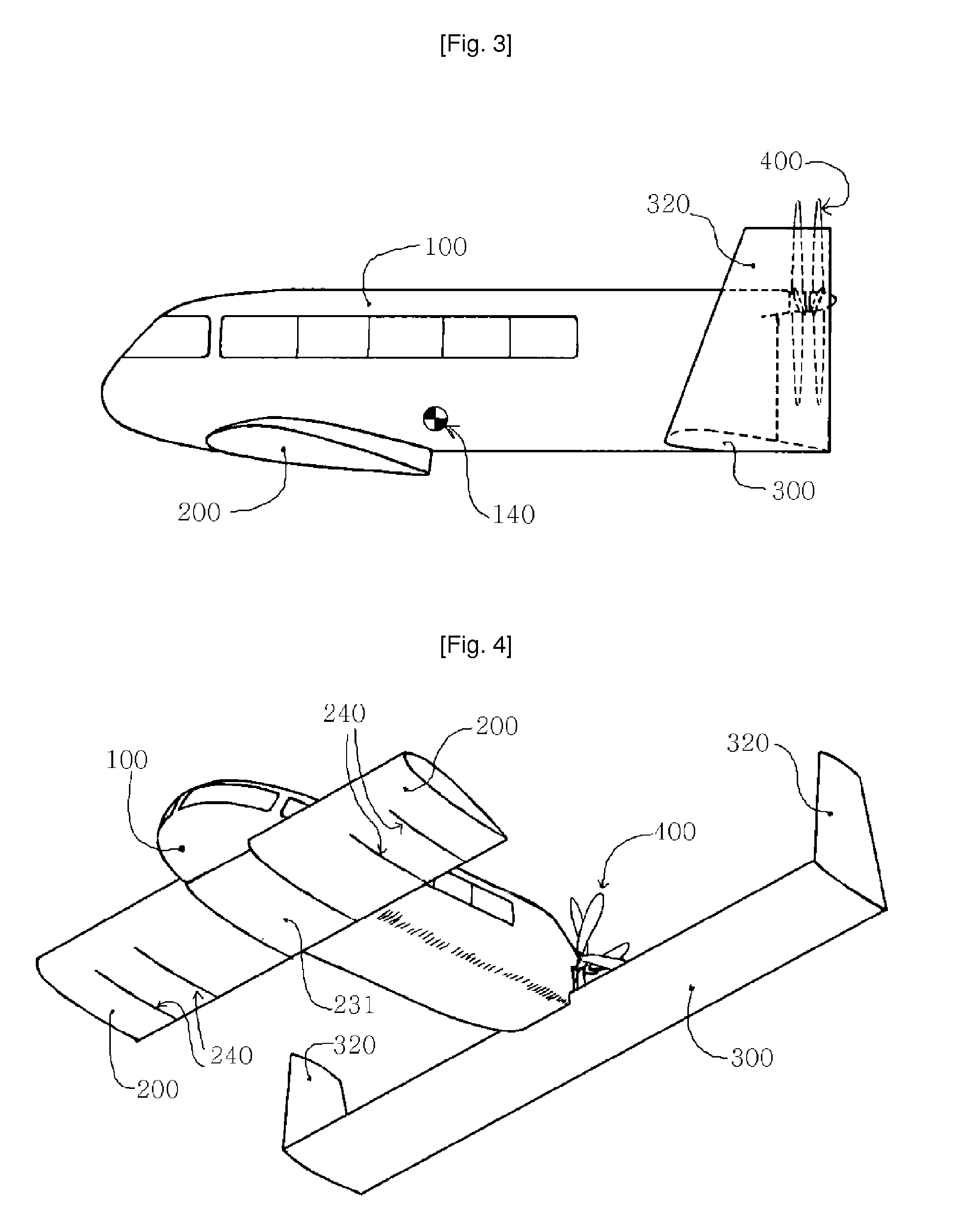
[0037]The first embodiment, which is the best mode to embody the present invention, is explained in detail by reference to FIG. 3 to FIG. 9.

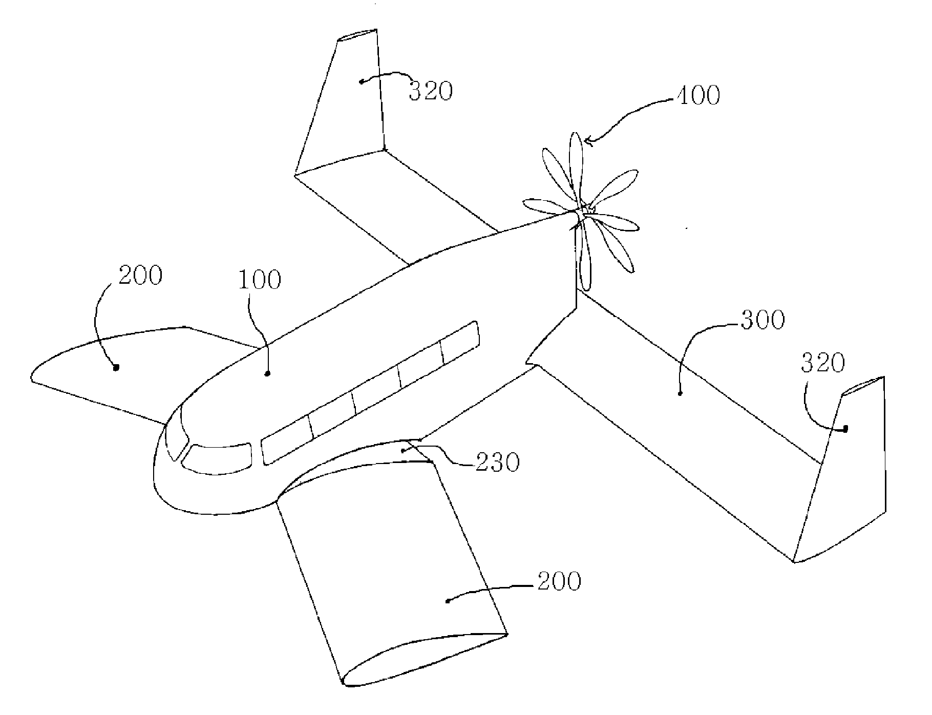
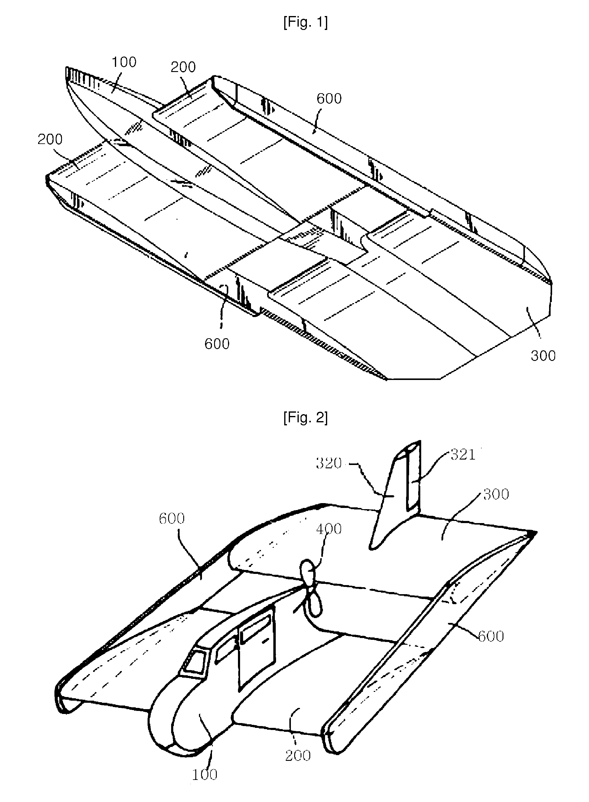
[0038]The body 100 of the WIG craft according to the present invention provides buoyancy when the WIG craft is stationary, and includes a boarding part into which passengers or freights are loaded.

[0039]The front wing 200 is installed in the lowest part of the fore half of the body 100 with the suspension system 230 installed between them. The front wing 200 is positioned in the lowest part of the WIG craft as shown in FIGS. 3 and 4. While the WIG craft is at rest, the front wing 200 provides buoyancy. And while the WIG craft takes off from and lands on the water, the front wing 200 provides hydrodynamic lift also with aerodynamic lift. And while the WIG craft is flying, the front wing 200 provides aerodynamic lift in ground effect. Its aspect ratio is in the range of 2˜5, and its thickness is around 16%. And it has a sufficient volume and its t...

second embodiment

[0063]The second embodiment of the WIG craft according to the present invention is explained by reference to FIG. 10.

[0064]The second embodiment is the same as the first embodiment except the point that a flexible flap is installed in the trailing edge of the front wing instead of installing a device to change the angle of incidence θ of the front wing 200. The flap 250 is made to be of a thin type. And it is divided into several sections, or it is made to have an elastic structure which can be somewhat twisted, to cover the cushion space tightly in the rough water surface. The first embodiment's function to change the anhedral angle Γ may be maintained or excluded according to circumstances. Explanation of what is the same as in the first embodiment is omitted, and only the differences between the first and the second embodiment and the effect resulting from them are explained.

[0065]In the second embodiment, the flap 250 sections are pivotaly installed in the trailing edge of the f...

third embodiment

[0068]Next, the third embodiment of the WIG craft according to the present invention is explained by reference to FIG. 11.

[0069]The third embodiment is the same as the first embodiment except that the front wing 200 has shock absorbing wingtip floats 270 instead of the device to change the anhedral angle Γ of the first embodiment and has the flap 250 of the second embodiment.

[0070]A pair floats 270 are installed through links (parallel crank 272, LM guide, etc.) at both ends of the front wing 200 of the third embodiment, and supported at a proper height by shock absorbers 271. Each shock absorber 271 comprises an air spring, a hydraulic damper and an expansion limiter. The configuration of the float 270 is a modification of a float for a common float plane as split in half right and left and it is made to have a sufficient height and length to prevent the cushion air from leaking sidewards. When the WIG craft starts to accelerate for taking off, the floats 270 are raised up along wi...


PUM


Abstract

This WIG craft has a configuration of tandem/canard type, comprising: a body; a front wing having a relatively small aspect ratio, as installed in the lowest portion of the fore half of the body; and a rear wing having a longer span and a shorter chord length than the front wing, as installed in the rearmost portion of the body. Since the front wing, which is also used for planing, is not fixed directly to the body, but installed through a suspension system, so as to travel up and down while planing along the rough water surface, the WIG craft can take off and land stably even in high waves, and further cruise at a extremely low height safely without worrying about the impacts of the wave.

Description

TECHNICAL FIELD[0001]The present invention relates to the WIG crafts flying just above the water surface using the ground effect, more particularly, a tandem or canard WIG craft having two wings arranged in the front and in the rear.BACKGROUND ART[0002]The WIG crafts use the ground effect that when the wing of a flying vehicle flies near the ground (or the water surface), the descent airflow gets to be screened by the ground (or the water surface), and thereby, the lift force gets to be increased and the drag gets to be decreased. Most modern high speed marine crafts have lift-to-drag ratios (L / D) of below 10 and most airplanes have lift-to-drag ratios of 10˜20. In comparison with them, the wig crafts using the ground effect can have lift-to-drag ratios of as high as 20˜30. Thus, the wig crafts have high fuel efficiency and can fly at the speed of general propeller aircrafts without being in direct contact with the water.[0003]The WIG craft having such features can perform various r...

Claims


Application Information

Patent Timeline
Patent Type & Authority Applications(United States)
IPC IPC(8): B63B1/16
CPCB60V3/06B60V1/08B63B1/18B64C35/001B64C35/008B64C39/12
Inventor LEE, HEE-SEOUNG
Owner LEE HEE SEOUNG
Why Eureka
Try Eureka