Micro-pilot injection ignition type gas engine

a gas engine and micro-pilot technology, which is applied in the direction of machines/engines, liquid fuel feeders, electric control, etc., can solve the problems of unstable engine speed fluctuations, easy to occur, and complicated starting mechanism of micro-pilot injection ignition type gas engine, etc., to achieve shorror the idling time span in the starting steps, and improve the precision

Active Publication Date: 2010-02-25
MITSUBISHI HEAVY IND ENGINE & TURBOCHARGER LTD
View PDF9 Cites 56 Cited by
  • Summary
  • Abstract
  • Description
  • Claims
  • Application Information

AI Technical Summary

Benefits of technology

[0022]In view of the above-stated conventional technology, the present invention is aiming at providing a micro-pilot injection ignition type gas engine, whereby an air fuel ratio control in starting the engine is execut...

Problems solved by technology

Thus, the starting mechanism of the micro-pilot injection ignition type gas engines is complicated.
Therefore, in starting the gas engine of the type, smooth combustion transition from a starting stage to a load operation stage is not so easy to be secured in comparison with other gas engines of different types.
Specifically, in the four-stroke cycle gas engines, fuel-gas and air are premixed and supplied to each main combustion chamber; further, in micro-pilot injection ignition type gas engines, at least one flame jet produced by the mentioned micro-pilot ignition system ignites the premixed air fuel mixture in the main chamber, and a lean-burn is performed; therefore, in the conventional gas engines of the type, engine speed fluctuations with unstable behavior are prone to occur, while the engine is in its starting process.
A prerequisite to secure an ignition performance and a starting performance as to the four-stroke cycle gas engines is to bring the air fuel ratio of the air fuel mixture in the main chamber c...

Method used


Image

  • Micro-pilot injection ignition type gas engine
  • Micro-pilot injection ignition type gas engine
  • Micro-pilot injection ignition type gas engine

Examples


Embodiment Construction

Best Mode for Carrying Out the Invention

[0083]Hereafter, the present invention will be described in detail with reference to the embodiments shown in the figures. However, the dimensions, materials, shape, the relative placement and so on of a component described in these embodiments shall not be construed as limiting the scope of the invention thereto, unless especially specific mention is made.

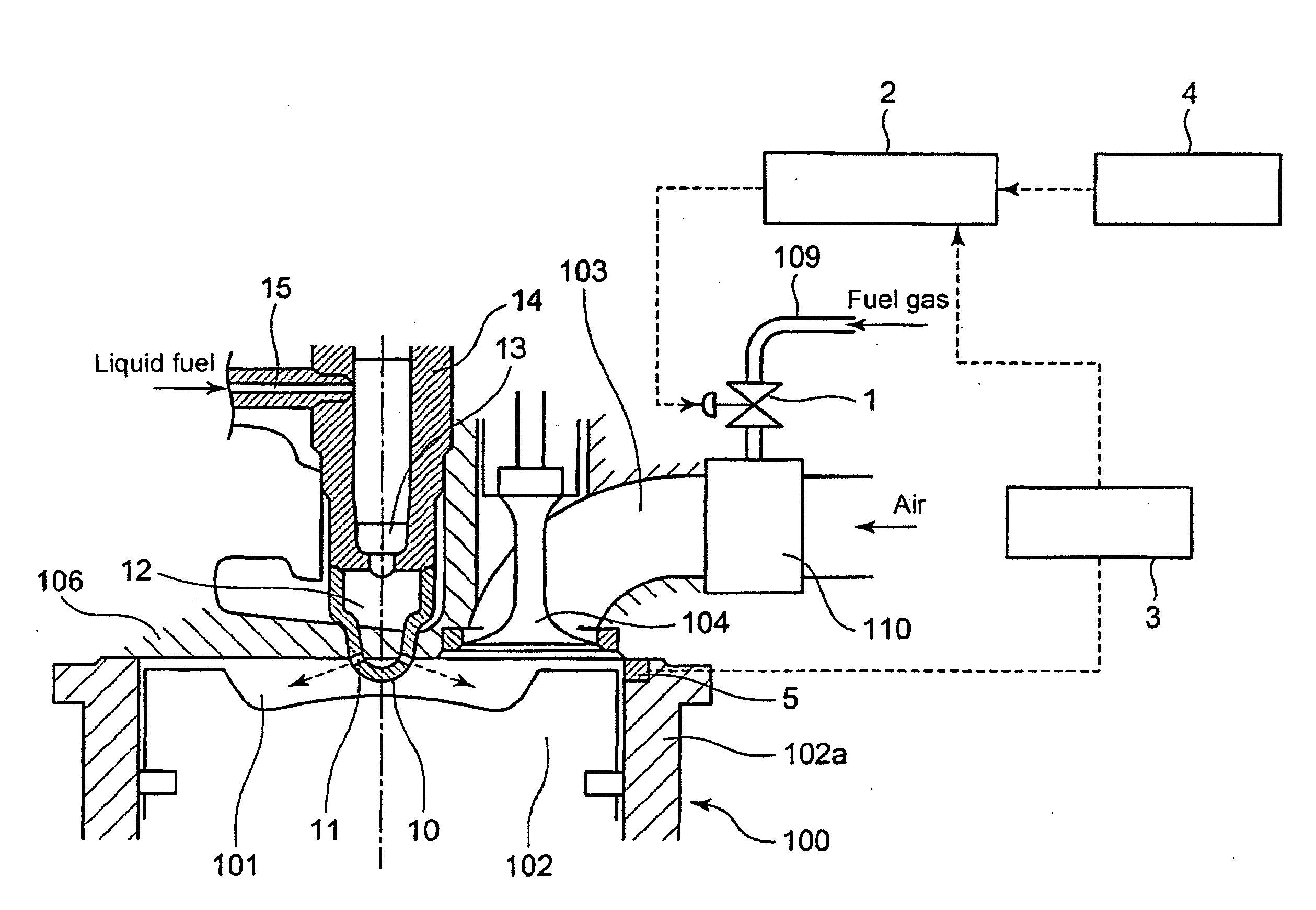
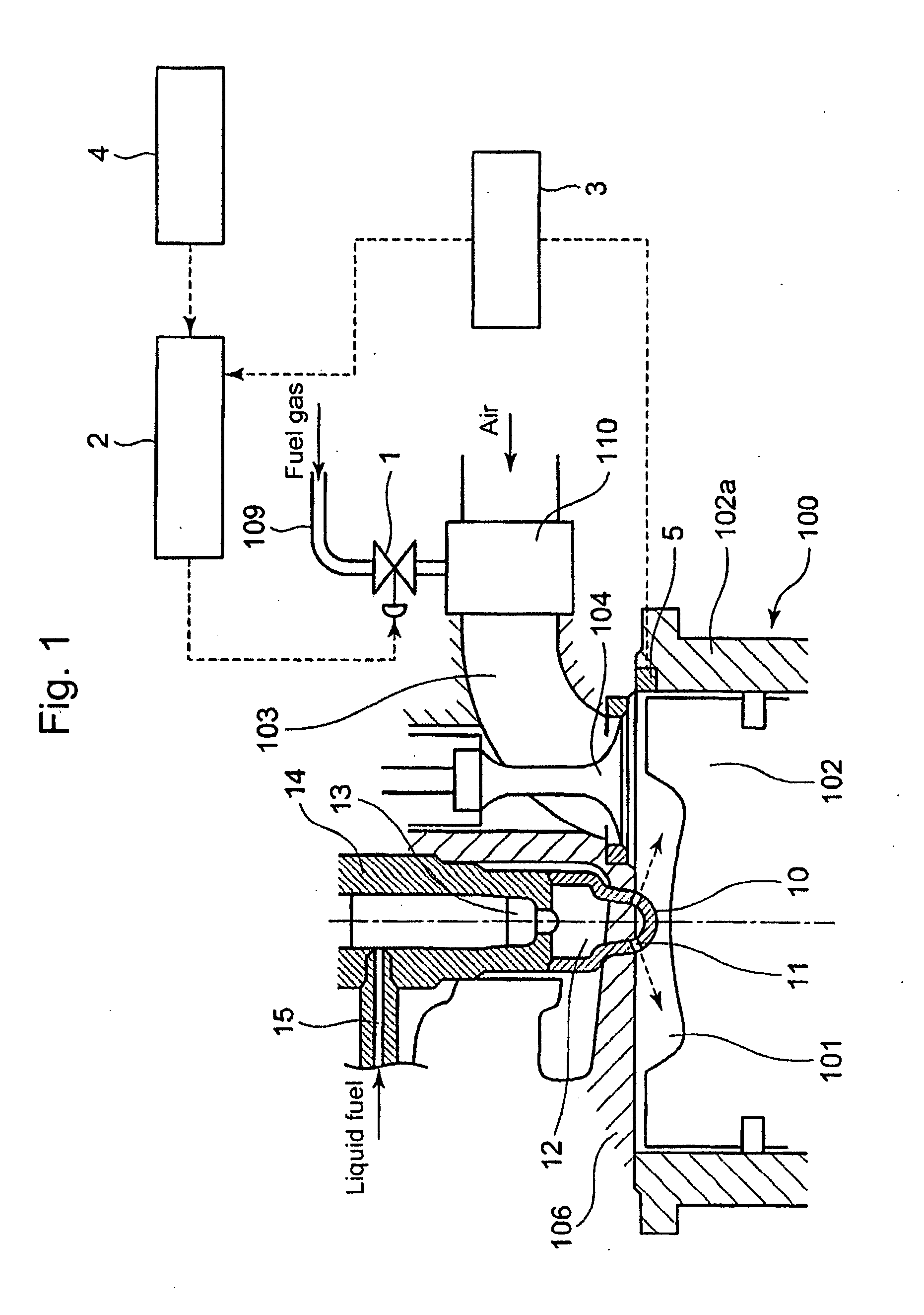
[0084]FIG. 1 shows a whole structure of a four-stroke cycle gas engine according to an embodiment of the present invention; whereby, the component depicted with Numeral 100 is a four-stroke cycle gas engine of a micro-pilot ignition type; Numeral 102a shows a cylinder-liner for each cylinder; Numeral 102 shows a reciprocating piston for each cylinder, and Numeral 106 shows a cylinder head for each cylinder; the bottom surface of the cylinder head 106, the upper surface of the piston 102, and the inner surface of the cylinder-liner 102a substantially form a main combustion chamber 101 to whic...


PUM


Abstract

What is disclosed is a micro-pilot injection ignition type gas engine, whereby an air fuel ratio control in starting the engine is executed with enhanced precision, by means of introducing skip-firing intermittent operations which reflect the engine operation conditions, while an idling time span can be shortened or omitted.
The engine includes: a gas valve that opens and closes a fuel-gas passage in front of each cylinder, so as to arbitrarily control the throat area as well as the opening-closing time span of the gas valve; an engine speed detecting unit to detect the engine speed; a combustion diagnosis unit to detect an engine combustion state through a cylinder pressure distribution along elapsed time, as to each cylinder; an opening-closing control unit as to the gas valve, so as to control the intermittent opening-closing of the gas valve according to the levels of the detected engine speed as well as the cylinder pressure distribution; whereby, in starting the engine, the intermittent opening-closing of the gas-valve enables at least one skip-firing mode that brings an enhanced fuel-supply pressure-pulsation with which a relatively large amount of fuel-gas is supplied per engine cycle with firing so that the air fuel-gas ratio of each cylinder reaches a prescribed target value.

Description

BACKGROUND OF THE INVENTION[0001]1. Technical Field[0002]The present application relates to a micro-pilot injection ignition type gas engine and an air fuel ratio control method thereof. The gas engine of the mentioned type inhales pre-mixed air fuel mixture into each cylinder, namely, into a main chamber, and initiates combustion of the mixture inside the main chamber with at least one pilot flame that jets out from a pre-chamber through at least one nozzle hole made in a pre-chamber housing, as an ignition-source for the mixture inside the main chamber; whereby the pilot flame jet is induced by means of combustion of an amount of micro-pilot fuel-oil that is injected through a pilot fuel injector as well as by means of combustion of a part of the air fuel mixture inhaled inside the pre-chamber from the main chamber through at least one nozzle hole. In the gas engines of the mentioned type, this application relates to an air fuel ratio control device that performs an open-close con...

Claims


Application Information

Patent Timeline
IPC IPC(8): F02B19/00F02M7/00F02M69/04F01L1/34
CPCF02B77/08F02B77/085F02D19/0631F02D19/10F02D35/023F02D19/0623F02D41/0087F02D41/06Y02T10/36F02D19/061F02D41/0025F02D41/0027F02D41/1454F02D41/1475F02D41/3047Y02T10/30F02B19/10F02D19/02F02D41/04F02M21/02
Inventor SUZUKI, HAJIMENISHIO, HIDEKISHIMIZU, YUUICHI
Owner MITSUBISHI HEAVY IND ENGINE & TURBOCHARGER LTD
Why Eureka
Try Eureka