Heat exchanger systems & fabrication methods

Inactive Publication Date: 2010-02-25
ALLSTYLE COIL
View PDF22 Cites 20 Cited by
  • Summary
  • Abstract
  • Description
  • Claims
  • Application Information

AI Technical Summary

Benefits of technology

[0014]In one aspect, in methods according to the present invention, less connection material (e.g. solder, brazing material or welding material) is needed to form an effective sealed joint between ends of a U-bend connector and tube ends of fluid flow tubes of a heat exchanger. Using less connection material and not having to expand the tube ends results in a less expensive, less labor intensive, less time consuming method of fabrication of a heat exchanger.
[0015]In certain aspects methods according to the present invention result in less distortion of fluid flow tubes' ends and less d

Problems solved by technology

It can be difficult to heat both tubes and materials uniformly with a single point heat source under certain time constraints, often causing a large temperature difference between materials of both tubes.
Temperature dependent bonding material, such as solder or adhesives, can be difficult to fill or distribute into a material connection due to a temperature difference between materials resulting from a single point heat source.
Also, melting points of solder may be exceeded or not achieved due to non-uniform temperatures in each of two tubes.
Melted solder bonds effectively to one material at a correct temperature and often only “covers” another material that is not at the required temperature (often resulting in an unacceptable bond).
Material that is not at the required temperature will impede the flow of adhesive and will not allow it to cover the entire surface of the “not-to-temperature-material” in the allotted time.
Overheating of one material to decrease the time it takes the other material to reach a necessary temperature can cause the heated material to become damaged or reach a melting

Method used


Image

  • Heat exchanger systems & fabrication methods
  • Heat exchanger systems & fabrication methods
  • Heat exchanger systems & fabrication methods

Examples


Embodiment Construction

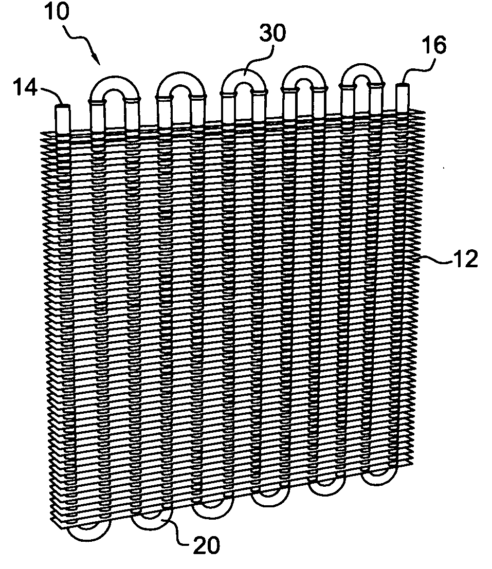
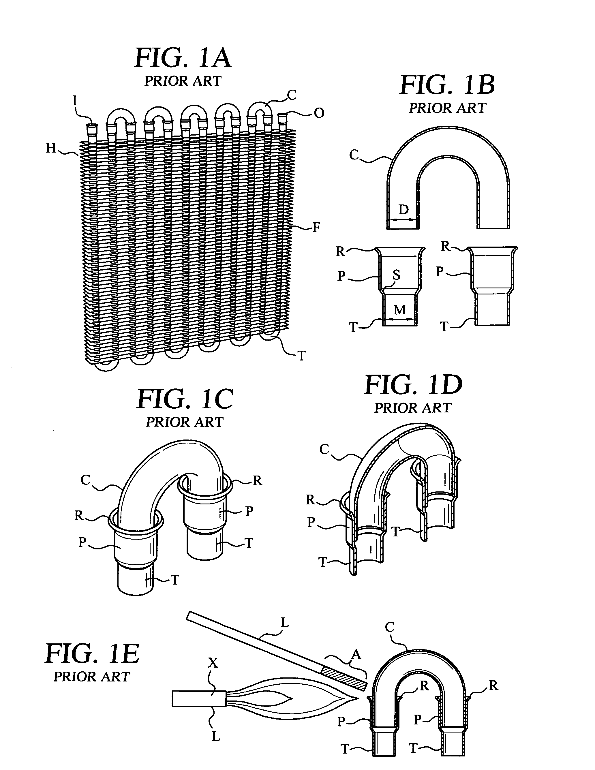
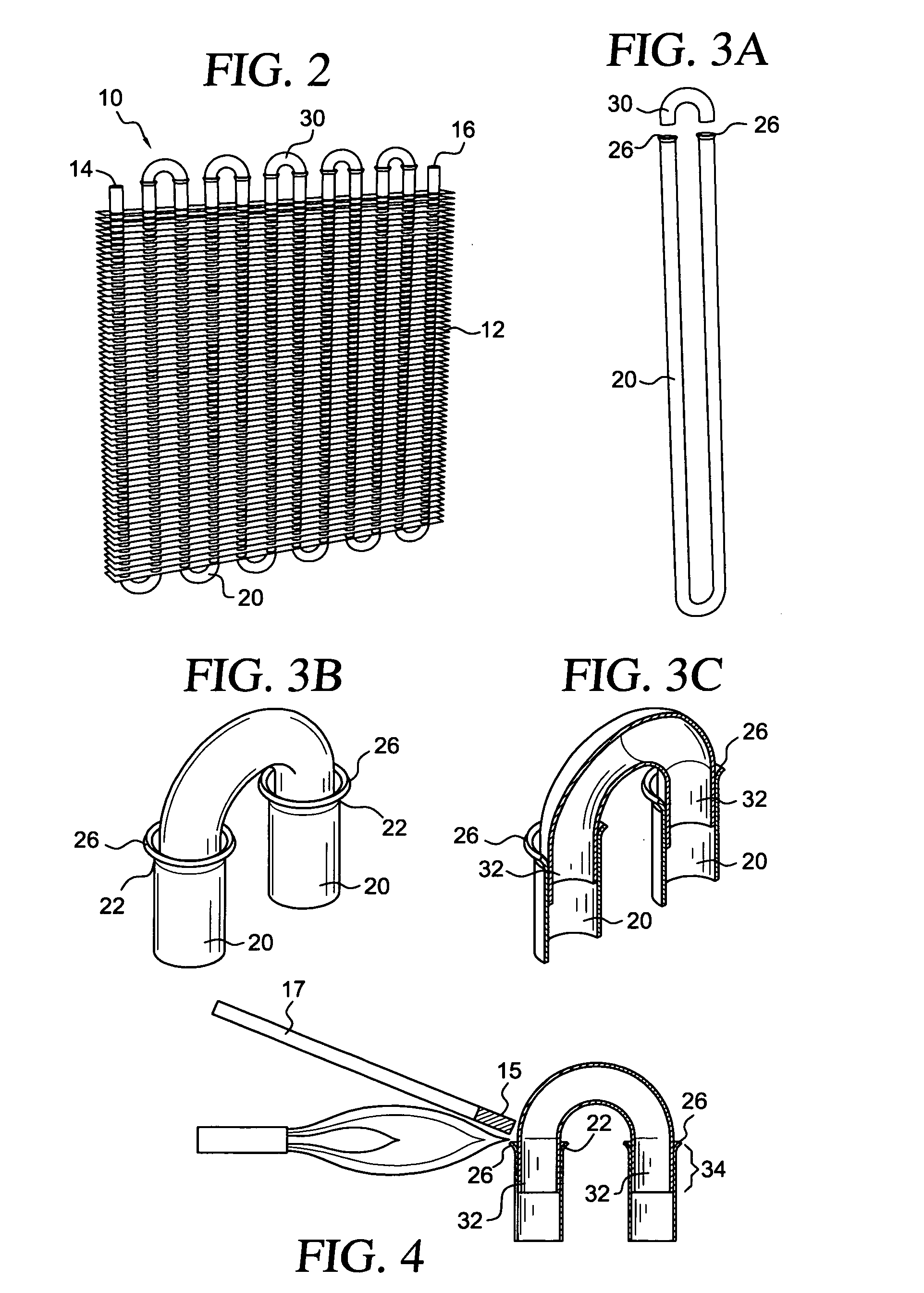
[0040]FIG. 1A shows a prior art heat exchanger H with tubes T through which heat exchange fluid flows and fins F in contact with the tubes T. Connectors C (“U-bend connectors”) connect adjacent ends of adjacent tubes T so that fluid is flowable from an inlet I to an outlet O through all the tubes T and the connectors C.

[0041]As shown in the FIGS. 1A-1E, each end of a tube T projecting from the upper most fin F has a flared portion R and an expanded portion P. In one aspect of prior art heat exchangers and, as shown in FIG. 1B, an inner diameter D of a connector C is substantially the same as the inner diameter M of the tubes T. To accommodate the outer diameter of the connectors C, the expanded portion P must be sufficiently wide to receive an end of a connector C. Expanding a tube end can result in stress that damages the tube end.

[0042]The flared portion R facilitates the initial entry of an end of a connector C into the expanded portion P. The ends of the connector C go down into...


PUM

PropertyMeasurementUnit
Fractionaaaaaaaaaa
Digital informationaaaaaaaaaa
Thicknessaaaaaaaaaa

Abstract

A heat exchanger with multiple tubes whose ends are connected with connectors to provide a flow path for heat exchange fluid through the heat exchanger. This Abstract is provided to comply with the rules requiring an abstract which will allow a searcher or other reader to quickly ascertain the subject matter of the technical disclosure and is submitted with the understanding that it will not be used to interpret or limit the scope or meaning of the claims, 37 C.F.R. 1.72(b).

Description

BACKGROUND OF THE INVENTION[0001]1. Field of the Invention[0002]This present invention is directed to heat exchanger systems, to methods for making heat exchangers, and, in certain particular aspects, to methods for joining U-bend connectors to ends of adjacent heat exchange tubes.[0003]2. Description of Related Art[0004]The prior art discloses a wide variety of heat exchangers, methods for making them, and methods for connecting ends of adjacent heat exchanged tubes including, but not limited to, the disclosures in U.S. Pat. Nos. 3,750,248; 3,877,519; 4,502,532; and 5,211,221 all incorporated fully herein for all purposes.[0005]U.S. Pat. No. 3,750,248 discloses method of making a refrigeration evaporator or condenser construction wherein the ends of preferably aluminum tubes which have been extended through heat exchange plates or fins in a refrigeration evaporator or condenser construction are joined with U-bend connectors, the method comprising forming radial internal beads near ...

Claims


Application Information

Patent Timeline
IPC IPC(8): F28F9/04B23P15/26
CPCF28D1/0477Y10T29/4938F28F9/26F28F1/32
Inventor CANALES, ANDRES ALBERTOMARTIN, SR., LENDELL
Owner ALLSTYLE COIL
Why Eureka
Try Eureka