Infrared detector with carbon nanotube yarns

Inactive Publication Date: 2010-02-25
HON HAI PRECISION IND CO LTD
View PDF1 Cites 9 Cited by
  • Summary
  • Abstract
  • Description
  • Claims
  • Application Information

AI Technical Summary

Problems solved by technology

Typical infrared detectors have co

Method used


Image

  • Infrared detector with carbon nanotube yarns
  • Infrared detector with carbon nanotube yarns
  • Infrared detector with carbon nanotube yarns

Examples


Embodiment Construction

[0010]Embodiments will now be described in detail below with reference to the drawings.

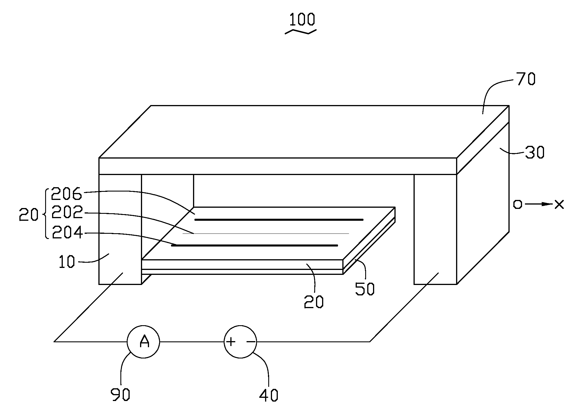
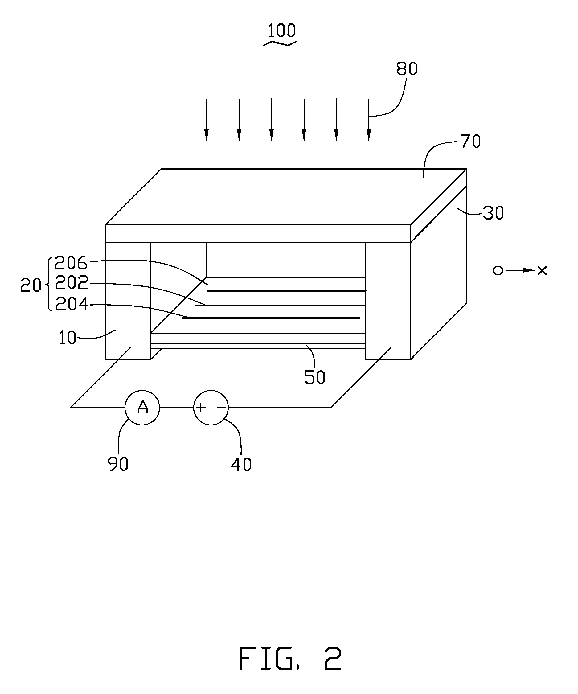
[0011]Referring to FIG. 1, an infrared detector 100 according to an exemplary embodiment is shown. The infrared detector 100 includes a first electrode 10, a second electrode 30 opposite to the first electrode 10, a composite film 20 between the first electrode 10 and the second electrode 20, a reflective film 50, a power supply 40, an ampere meter 90 and an infrared band-pass filter 70.

[0012]The power supply 40 includes a positive electrode and a negative electrode connecting with the first electrode 10 and the second electrode 30, respectively. A first end of the composite film 20 is electrically connected with the first electrode 10, and an opposite second end of the composite film 20 and the second electrode 30 cooperatively define a gap. The reflective film 50 is formed on a surface of the composite film 20. The infrared band-pass filter 70 is supported by the first and the second electrodes ...


PUM


Abstract

An infrared detector based on CNT yarns includes a first electrode, a second electrode and a composite film between the first electrode and the second electrode. A first end of the composite film is electrically connected to the first electrode. A second end of the composite film and the second electrode cooperatively define a gap therebetween. The composite film is capable of extending in a direction towards the second electrode and, thereby forming an electrical connection between the first and the second electrodes when the composite film is illuminated by infrared light. The composite film includes a polymer layer, a plurality of semiconducting CNT yarns dispersed in the polymer layer, and a plurality of metallic CNT yarns dispersed in the polymer layer. Each semiconducting CNT yarn includes a plurality of twisted semiconducting CNTs. Each metallic CNT yarn includes a plurality of twisted metallic CNTs.

Description

CROSS-REFERENCE TO RELATED APPLICATION[0001]This application is related to a commonly-assigned copending application, Ser. No. ______, entitled “ACTUATOR WITH CARBON NANOTUBE YARNS” (attorney docket number: U.S. Pat. No. 21,870). Disclosures of the above-identified application are incorporated herein by reference.BACKGROUND[0002]1. Technical Field[0003]The present invention relates to infrared detectors, and particularly to an infrared detector with carbon nanotube (CNT) yarns.[0004]2. Description of Related Art[0005]Infrared radiation is used in a number of applications in the fields of industry, agriculture, medicine, science, communications, and remote sending from space. Infrared detectors have been employed in a variety of fields, such as human body detection, fire detectors, and etc. Typical infrared detectors have complex structures and are expensive.[0006]Therefore, a new infrared detector is desired to overcome the above mentioned problems.BRIEF DESCRIPTION OF THE DRAWINGS[...

Claims


Application Information

Patent Timeline
IPC IPC(8): H01L31/028
CPCB82Y10/00H01L27/305Y02E10/549H01L51/4253H01L51/0048H10K39/30H10K85/221H10K30/30
Inventor HUNG, HSIN-CHIN
Owner HON HAI PRECISION IND CO LTD
Why Eureka
Try Eureka