Field emission element having carbon nanotube and manufacturing method thereof

a carbon nanotube and emission element technology, applied in the manufacture of electric discharge tubes/lamps, discharge tubes luminescnet screens, electrode systems, etc., can solve the problems of poor electrical connection between the conductive base and the carbon nanotube, general unsatisfactory field emission characteristics of the carbon nanotube, and low precision and efficiency of the

Active Publication Date: 2007-12-27
TSINGHUA UNIV +1
View PDF22 Cites 13 Cited by
  • Summary
  • Abstract
  • Description
  • Claims
  • Application Information

AI Technical Summary

Problems solved by technology

However, the precision and efficiency thereof are relatively low.
Furthermore, the electrical connection between the conductive base and the carbon nanotube tends to be poor because of the limitations of the conductive adhesives/pastes used therebetween.
Thus, the field emission characteristics of the carbon nanotube are generally unsatisfactory.
However, the mechanical connection between the carbon nanotube and the conductive base often is relatively weak and thu...

Method used


Image

  • Field emission element having carbon nanotube and manufacturing method thereof
  • Field emission element having carbon nanotube and manufacturing method thereof
  • Field emission element having carbon nanotube and manufacturing method thereof

Examples


Embodiment Construction

[0018]Reference will now be made to the drawings to describe embodiments of the present field emission element and the related manufacturing method, in detail.

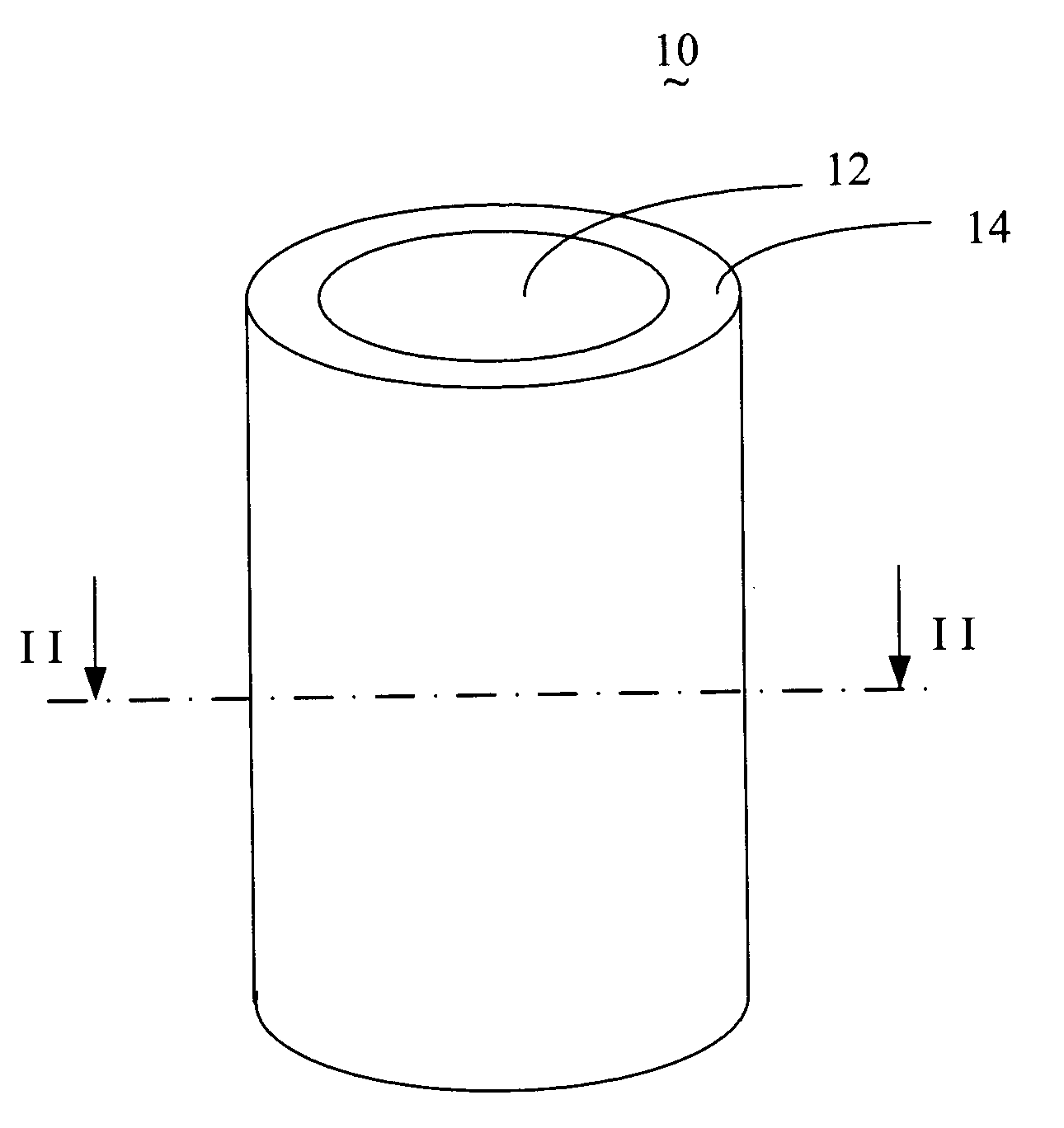
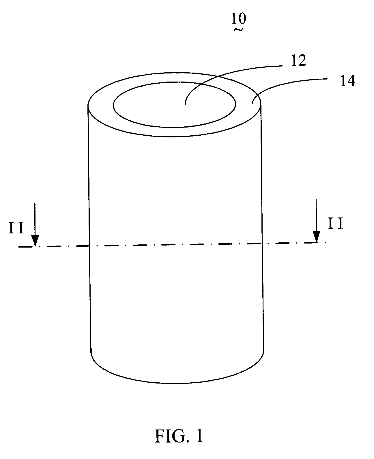
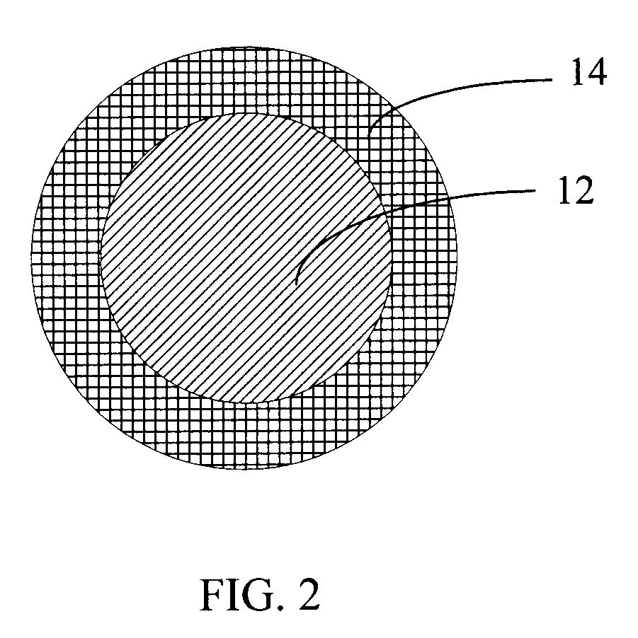
[0019]FIG. 1 is an isometric view of a field emission element 10, in accordance with an exemplary embodiment of the present device, and FIG. 2 is a cross-sectional view of the upper portion of the field emission element 10 of FIG. 1. As shown in FIGS. 1 and 2, the field emission element 10 illustrated includes one carbon nanotube field emission wire 12 and a supporting protective layer 14 coating an outer surface of the carbon nanotube field emission wire 12. The carbon nanotube field emission wire 12 is used for emitting electrons, and the supporting protective layer 14 is configured (i.e., structured and arranged) for supporting and protecting the carbon nanotube field emission wire 12. The supporting protective layer, beneficially, further may, at least in part, help to attach / bond the field emission element 10 to a corresp...


PUM


Abstract

A given field emission element includes a carbon nanotube field emission wire and at least one supporting protective layer coating an outer surface of the carbon nanotube field emission wire. The carbon nanotube field emission wire is selected from a group consisting of a carbon nanotube yarn, a wire-shaped CNT-polymer composite, and a wire-shaped CNT-glass composite. A method for manufacturing the described field emission element includes the steps of: (a) providing one carbon nanotube field emission wire; (b) forming one supporting protective layer on an outer surface of the carbon nanotube field emission wire; and (c) cutting the carbon nanotube field emission wire to a predetermined length and treating the carbon nanotube emission wire to form the field emission element.

Description

RELATED APPLICATIONS[0001]This application is related to a commonly-assigned application entitled, “FIELD EMISSION ELEMENT HAVING CARBON NANOTUBE AND MANUFACTURING METHOD THEREOF”, filed ______ (Atty. Docket No. US11284), the content of which is hereby incorporated by reference thereto.BACKGROUND OF THE INVENTION[0002]1. Field of the Invention[0003]The invention relates to field emission elements and manufacturing methods thereof and, particularly, to a field emission element employing carbon nanotubes and a manufacturing method thereof.[0004]2. Description of Related Art[0005]Carbon nanotubes (CNTs) produced by means of arc discharge between graphite rods were first discovered and reported in an article by Sumio Iijima, entitled “Helical Microtubules of Graphitic Carbon” (Nature, Vol. 354, Nov. 7, 1991, pp. 56-58). Carbon nanotubes are electrically conductive along their length, are chemically stable, and can each have a very small diameter (much less than 100 nanometers) and a lar...

Claims


Application Information

Patent Timeline
IPC IPC(8): H01J1/00H01J19/06
CPCB82Y10/00H01J2201/30469H01J9/025H01J1/304
Inventor LIU, LIANGJIANG, KAI-LIFAN, SHOU-SHANCHEN, CAESARLEE, HSI-FUCHEN, GA-LANE
Owner TSINGHUA UNIV
Why Eureka
Try Eureka