Modular lamp head and assembly for non-destructive testing

a module lamp and non-destructive technology, applied in the field of modules for non-destructive testing, can solve the problems of low light intensity, dangerous darkness, and the loss of fluorescence ability of fluorescent materials,

Active Publication Date: 2010-02-25
SPECTRO UV LLC
View PDF11 Cites 71 Cited by
  • Summary
  • Abstract
  • Description
  • Claims
  • Application Information

AI Technical Summary

Benefits of technology

[0017]The module body may include one or more heat fins for dissipating heat from the light emitting diodes. The fan is preferable mounted to the housing so as to draw heat from the fins.

Problems solved by technology

A fluorescent material will also lose the ability to fluoresce when the incident light does not have enough energy within the specific excitation range.
Unfortunately, visible (including ambient) light competes with the fluorescence from dye for the attention of the person conducting the test.
When performed in total darkness, the outcome of such a procedure is often enhanced; however, total darkness is often not available in testing environments, such as an outdoor air conditioner where the sun cannot be shut off, or a shop floor where darkness may be dangerous when machinery in motion is involved.
A very small fault is often difficult to detect even though such a small fault may present a potentially great danger.
Existing ultraviolet lamps have several weaknesses.
Some concerns with existing ultraviolet lamps are their cost, size, and power consumption.
However, fluorescent lamps generate a low intensity of incident ultraviolet radiation.
This is often difficult in the tight spaces available when working around machinery and equipment.
However, the small area of illumination generated by the lamp makes inspection of larger areas more time consuming.
More particularly, the narrow width of the unit permits light from the surrounding environment to sometimes overpower the fluorescent response in brightly lit rooms, thus making detection difficult.
The narrow width of light also has limited usage in the field of non-destructive testing where typically large areas are being tested for faults.
Halide lamps are currently in common use in non-destructive testing (NDT), but halide lamps get very hot and project light covering a wide wavelength.
To accommodate for the wide wavelength coverage, expensive filters are used to remove the unneeded wavelengths of light and project the proper wavelength needed for testing.
Since the filters are absorbing or reflecting light, they tend to heat up the ambient air surrounding the lamp.

Method used


Image

  • Modular lamp head and assembly for non-destructive testing
  • Modular lamp head and assembly for non-destructive testing
  • Modular lamp head and assembly for non-destructive testing

Examples


Embodiment Construction

[0035]It will be appreciated by those skilled in the art that the present invention may be practiced in various forms and configurations. This detailed description of the disclosed embodiments is presented for purposes of clarity of understanding only, and no unnecessary limitations should be implied therefrom.

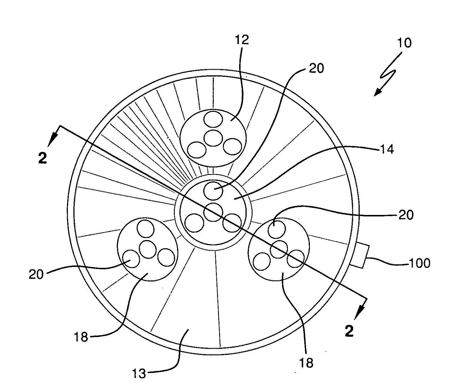
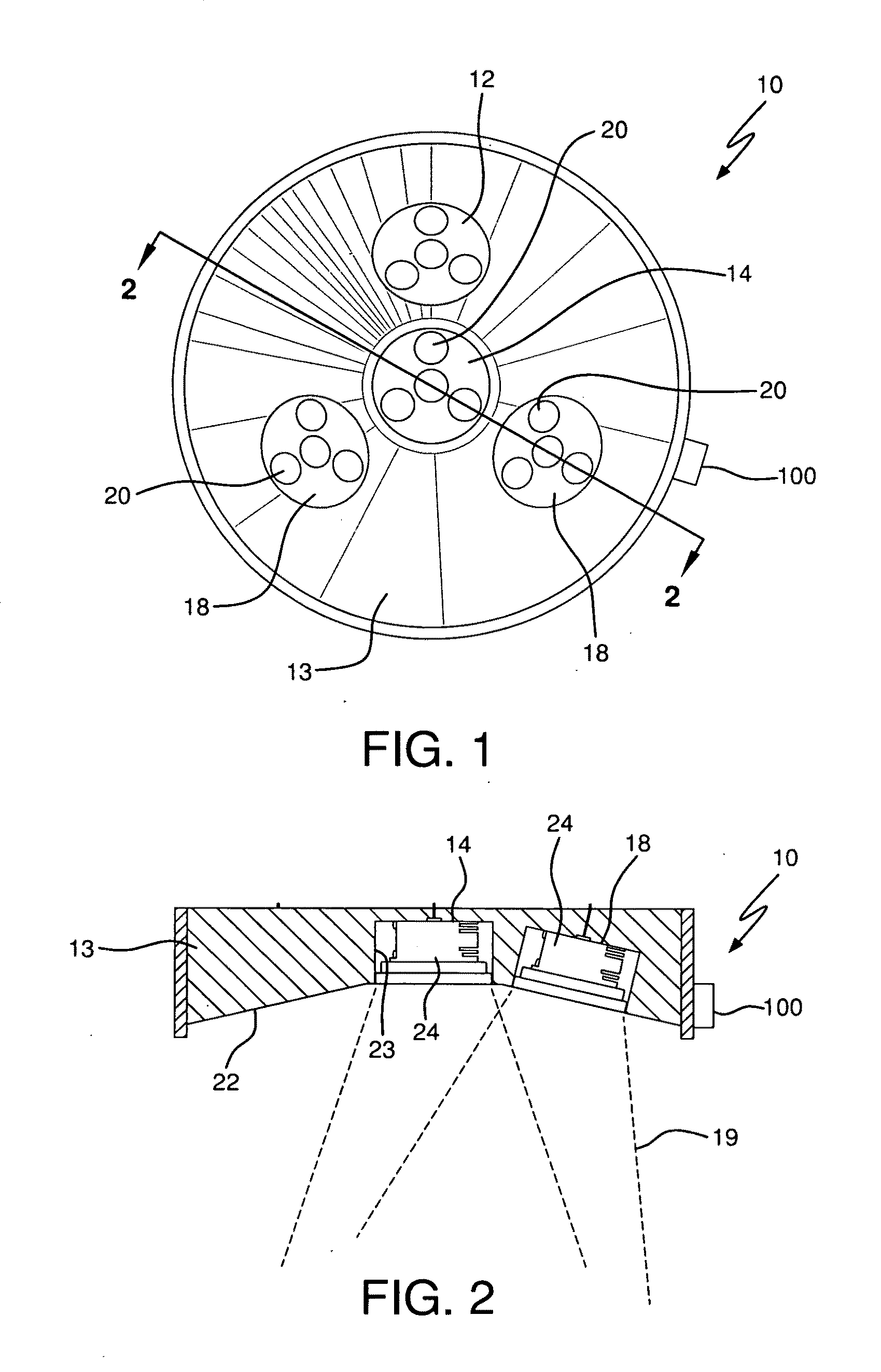
[0036]Referring to FIG. 1, one embodiment of a lamp or lamp assembly 10 is shown which includes a plurality of modular heads or modules 12 mounted in a housing 13, each module including at least one light-emitting diode (LED). In one embodiment, the lamp assembly preferably includes a central module 14 containing at least one white LED 20 emitting full or substantially full spectrum (white) light. One or more peripheral modules 18 are oriented around the central module. In one embodiment, the lamp preferably includes three peripheral modules arranged in a triangular pattern around the central module; however, one of ordinary skill in the art will realize that the peripheral mo...


PUM


Abstract

A lamp module for use in non-destructive testing and inspection. The module including a module body with a front and rear end, and a side wall. The module body includes a mounting chamber located within the side walls. A plurality of LEDs are mounted within the chamber and oriented to so as to emit light out of the front end of the body. At least one LED emits light having a wavelength selected to produce fluorescence of an illuminated material. A fan is mounted to the body to dissipate heat generated by the LEDs when the fan is activated. Electrical connectors extend out of the body and are electrically connected to the LEDs and the fan for supplying current. The module can be installed in various structures or systems, including in a luminaire, an overhead light housing or a track light system.

Description

RELATED APPLICATIONS[0001]This application is related to and claims priority from U.S. Provisional Patent Application 61 / 189,397 filed Aug. 19, 2008 and U.S. Provisional Patent Application 61 / 203,037 filed Dec. 17, 2008, the disclosures of which are both incorporated herein by reference in their entirety.FIELD OF INVENTION[0002]The present invention relates to lamps, and especially, but not exclusively, to a modular lamp for use in non-destructive testing.BACKGROUND[0003]Fluorescence is generally understood to be a property that enables certain materials to absorb light energy and radiate visible light at a longer wavelength than the absorbed light. Without being limited to any specific theory, it is widely accepted that electrons in fluorescent materials are excited upon being illuminated by light energy of a specific wavelength, and light energy of a longer wavelength is radiated from these materials as the electrons return to the unexcited or ground state. The specific excitation...

Claims


Application Information

Patent Timeline
Patent Type & Authority Applications(United States)
IPC IPC(8): B01J19/12
CPCF21K9/00F21V29/02F21V29/20G01N21/6447G01N21/91F21Y2101/02F21Y2115/10F21V29/677F21V29/74F21V29/61
Inventor GARCIA, GUSTAVODUERR, JOHNSU, CHIH-TSUNG
Owner SPECTRO UV LLC
Why Eureka
Try Eureka